


3-3
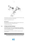
front, rear, and each of the sides of the unit. The three black screws should
be reserved for affixing at the front.
Note The front panel is attached to the top cover by means of 4 screws also affixing the
handles. These do not need to be removed.
By grasping the front panel handles, gently pull the top cover/front panel
assembly forward then away towards the rear. Carefully set aside this sub-
assembly.
Reverse the above procedure when re-assembling the unit.
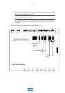
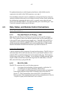
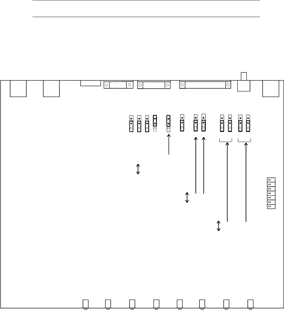
S101
J200
DP524 MOTHERBOARD
1
[ON]
OFF
Signal Ground to
Chassis Ground Link
[Open]
Linked
J103
J201
J202
J203
J204
J3
J205
J206
RT RD
J209
J210
J207
J208
TR
RS
[Terminated (150 ohm)]
Not Terminated
J105
Note: Jumpers J200, 201, 202, 203,204
are not applicable to this product and should
not be disturbed. Leave them in the positions
shown.
MAIN