


Introduction
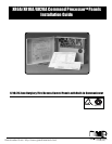
XR6A/XR10A/XR20A Installation Guide
Digital Monitoring Products 2841 E. Industrial Drive Springfield, MO USA 65802-6310 800-641-4282
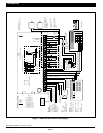
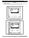
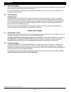
Figure 1: XR6A/XR10A/XR20A wiring diagram
Page 4
Refer to the Command
ProcessorTM Panel
Programming and Installation
Guides for a complete
description of programming
instructions and wiring
connections.
Secondary
Battery Power
1.2 Amps max.
charging current.
Use only 12 VDC
rechargable batteries.
DMP Model 367.
Replace every
3 - 5 years.
Bell
10.4 - 13.2 VDC
Total current:
1.5 Amps max. w/ 40 VA
600mA w/ 20 VA
Keypads
Models 670. 770, 771,
100mA @ 8 - 16 VDC
125mA with display lit
Models 690, 790, 791,
793
100mA @ 8 - 16 VDC
Model 692
75mA @ 8 -16 VDC
XR6A
XR10A
XR20A
WIRING DIAGRAM
Tamper protection wh
required for Model 34
9
Attack Resistant
Enclosure.
Zone 10 compatibility
identifier: A
Maximum operating
range: 8.8 VDC - 14.
2
VDC.
Heat detectors, manual pull stations, or
any other shorting device. Unlimited
number of units.
Up to 500mA auxiliary
current at 10.4 - 13.2
VDC from Terminal 7.
Cold Water Pipe
Earth Ground
Maximum AC wire distance
With 16 gauge wire: 70 feet
With 18 gauge wire: 40 feet
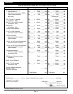
Primary Power
16 VAC
20 or 40 VA
16 - 18 gauge wire
Bell
Power
Supervision
Relay
Smoke Output
100mA @ 10.4 - 13.2 VDC Terminal 11
Smoke
Detector
Output Header J11
Use DMP Model 300 Harnes
Front Tamper
Rear Tamper
LT-0449 (5/99)
3.3k DMP Model 309
ACN 087 480 279
2-wire
smoke
detector
Phone Jack Connector
J4
J16
Command Processor Reset
For XR6A terminal block zone wiring
For XR10A and XR20A terminal block zone wiring
EPROM
Sock
et
U11
Red
Black
4-wire smoke detector
J11
1
2
3
4
1K
1K 1K 1K 1K 1K
RED
BLACK
ZONE 10
ZONE 9
ZONE 8
ZONE 7
ZONE 6
ZONE 5
ZONE 1
ZONE 2
ZONE 3
ZONE 4
22 GA. MIN
BLACK
22 GA. MIN
RED
22 GA. MIN
YELLOW
22 GA. MIN
GREEN
+ -
ZON
E
6
ZON
E
5
ZON
E
1
ZON
E
2
ZON
E
3
ZON
E
4
AC AC +B -B BELL GND RED YEL GRN BLK SMK Z1 GND Z2 Z3 GND Z4 Z5 GND Z6 Z7 GND Z8 Z9 Z10+ Z10-
1K 1K 1K