


Installation
XR6A/XR10A/XR20A Installation Guide
Digital Monitoring Products 2841 E. Industrial Drive Springfield, MO USA 65802-6310 800-641-4282
Burglary Zones
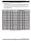
10.1 Description
The XR10A/XR20A terminals 12 to 24 are the nine burglary zones. For programming purposes, the zone
numbers are 1 to 9. The zone configurations on terminals 12 to 24 are described below. The XR6A terminals 12
to 18 are the five burglary zones with terminal 16 providing the ground for zone 5.
Terminal Function Terminal Function
12 Zone 1 voltage sensing 19 Ground for zones 5 & 6
13 Ground for zones 1 & 2 20 Zone 6 voltage sensing
14 Zone 2 voltage sensing 21 Zone 7 voltage sensing
15 Zone 3 voltage sensing 22 Ground for zones 7, 8, & 9
16 Ground for zones 3 & 4 (& 5 on XR6A) 23 Zone 8 voltage sensing
17 Zone 4 voltage sensing 24 Zone 9 voltage sensing
18 Zone 5 voltage sensing
The voltage sensing terminal measures the voltage flowing through the 1k W End Of Line resistor to the zone's
ground terminal. Dry contact sensing devices can be used in series (normally-closed) or in parallel (normally-
open) with any of the burglary protection zones.
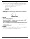
10.2 Operational parameters
Each burglary protection zone detects three conditions: open, normal, and short.
The parameters for each are listed below:
Condition Resistance on zone Voltage on right terminal
Open over 1300 ohms over 2.0 VDC
Normal 600 to 1300 ohms 1.2 to 2.0 VDC
Short under 600 ohms under 1.2 VDC
10.3 Zone response time
A condition must be present on a zone for 500 milliseconds before it's detected by the XR6A/XR10A/XR20A
panel. Ensure detection devices used on the protection zones are rated for use with this delay.
10.4 Keyswitch arming zone
Momentary keyswitches
You can use a momentary keyswitch on a zone programmed as an Arming type for use in arming and disarming
the system without a code.
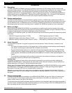
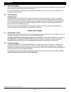
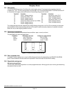
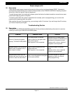
1K
NORMALLY CLOSED CONTACTS NORMALLY OPEN CONTACTS COMBINATION: NORMALLY OPEN AND
NORMALLY CLOSED CONTACTS
1K
1K
Figure 3: Protection zone contact wiring
Page 10