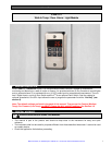
dIXEL&
Operating Instructions XWA11V
1598003200
Weiss Instruments, Inc. 905 Waverly Ave. Holtsville, NY 11742 631-207-1200 www.weissinstruments.com
4
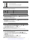
5.2.2 HOW TO MOVE A PARAMETER FROM THE HIDDEN MENU TO THE FIRST LEVEL AND
VICEVERSA
Each parameter present in the HIDDEN MENU can be removed or put into “THE FIRST LEVEL” (user level)
by pressing “SET + down”.
In HIDDEN MENU when a parameter is present in First Level the decimal point LED is on.
5.3 HOW TO LOCK THE KEYBOARD
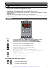
1. Keep pressed for more than 3s the UP and DOWN keys.
2. The “POF” message will be displayed and the keyboard will be locked. At this point it will be possible
only to see the Set Point or the MAX o MIN Temp stored
3. If a key is pressed more than 3s the “POF” message will be displayed.
5.4 TO UNLOCK THE KEYBOARD
Keep pressed together for more than 3s the UP and DOWN keys. The “PON” message is displayed
6. LIGHT MANAGEMENT
6.1 TIMED REGULATION: I1L = Y
With i1L = y the light remains on at least for the LHt parameter.
The LHt timer is re-initialized every time the light button is pushed.
With LHt=0 the light remains on until the light button is pushed again.
The light is switched on every time one of the following conditions happens:
• the door is open (i1F = dor)
• the presence sensor is activated (i2F = LHt)
• the light button is pushed
The light is switched off when all the following conditions happen:
• the LHt timer is exhausted
• the door is closed (i1F = dor)
• the presence sensor is de-activated (i2F = LHt)
• Light button regulation: i1L = n
The light button has a higher priority than digital inputs therefore:
- if the light was switched on by button the digital input can not modify its status.
- if the light was switched on by digital input, the light button can modify its status.
7. INSTALLATION AND MOUNTING
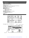
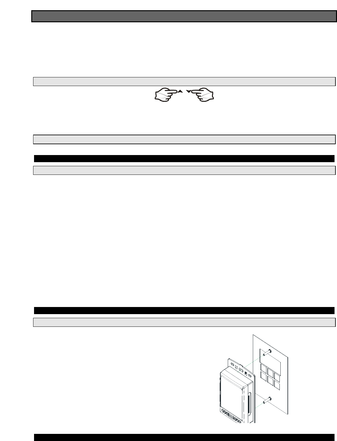
7.1 MOUNTING OF XWA11V – PR10000
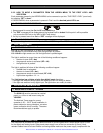
The XWA11V must be mounted on vertical
panel, in a J-Box or wall mount using the
VS-BOX2
The Ambient Temp range for correct
operation is 32 – 140°F. Avoid installation in
places subject to strong vibrations, corrosive
gases, excessive dirt or humidity. The same
recommendations apply to probes.
8. ELECTRICAL CONNECTIONS
The instrument is provided with screw terminal blocks to connect cables with a cross section up to 2,5 mm
2
for the digital and analog inputs. Relays and power supply have a Fast-on connection (6,3mm). Heat-
resistant cables have to be used. Before connecting cables make sure the power supply complies with the


