


11
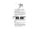
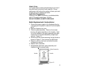
Figure 7
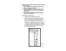
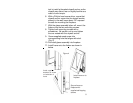
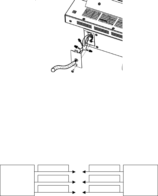
7. Route the power supply wire through the
knockout on supplied alternative junction box
cover and secure with a wire clamp (not
supplied) (FIGURE 7.)
8. Connect the black wire (live) from the unit to the
black wire from power supply. (FIGURE 7.)
9. Connect the white wire (neutral) from the unit to
the white wire from power supply. (FIGURE 7.)
10. Connect the green wire (ground) from the unit
to the green wire from power supply.
(FIGURE 7.)
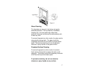
120V
POWER
SUPPLY
(BREAKER
PANEL)
FIREPLACE
JUNCTION
BOX
WHITE WIRE (N)
WHITE WIRE (N)
BLACK WIRE (L) BLACK WIRE (L)
GREEN WIRE (G)
GREEN WIRE (G)
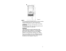
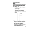
11. Place all connectors inside the unit and secure
the junction box cover to unit. Ensure that the
cable clamp grips only the jacket of service
cable.
NOTE
All wiring must be completed prior to installing
the unit into the wall.
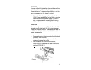
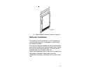
12. Place unit in position in the opening, push
straight in and attach unit to studs using No. 10
fasteners. Attach supplied wall cover brackets
to the top and the bottom of fireplace to cover
the gap on the dry wall (Figure 8)