


This section provides step by step instructions for selecting
a location and preparing the site to install the fireplace into
the following:
Existing Fireplace
1. Make sure that the fire is located on a flat surface.
2. Seal all draughts and vents to prevent chimney debris
from falling onto the Fireplace Insert. Do not install into an
existing fireplace that is prone to dampness.
3. Remove the fire front panel by following the steps as
outlined in ‘Lamp Replacement’ sections.
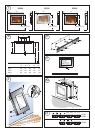
4. Locate the 4 fixing holes, position the fire accordingly,
and firmly fix the appliance to the wall using the appropriate
screws - see Fig. 5a.
5. Replace the front panel.
New Support Structure Construction
When planning where to position your purpose built support
structure the following steps must be observed:
1. Place the fire in the desired location to see how it will
look in the room.
2. Mark the desired location for the new support structure
in the room and store the fire in a safe, dry and dust free
location.
3. Using timber studs to support the fire, devise and
construct a suitable means of supporting the product within
the wall partition and provide electrical power for the fire to
be HARD wired. For recommended sizes of height, width
and depth of opening for recess and hole fixing dimensions
for each model - see Table 1 and Fig. 5a.
4. When the structure is complete, remove the front panel
of the fire by following the steps as outlined in ‘Lamp
Replacement’ sections.
5. Locate the 4 fixing holes, position the fire accordingly,
and firmly fix using the appropriate screws.
6. Replace the front panel.
TABLE 1
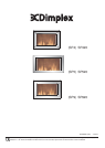
Models A B X Y Z
SP420 871 570 847 646 115
SP520 1160 560 1143 640 146
SP920 914 565 895 676 150
NOTE: The appliance should be HARD wired to an electrical
power outlet when placed in a recessed installation.
Please consult a qualified electrician for appropriate wiring
requirements.
Manual Operation - SP420 & SP920
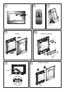
The switches are located at the bottom right side of the heater.
The Standby Switch (Switch S1) must be first turned ‘ON’ and
the AUTO/MAN (Switch S2) switch set to ‘MANUAL’ to operate
the manual controls - see Fig. 6.
Note : When the fire is put in Manual mode the first time the
flame effect will come on indicated by the Bottom neon coming
on for 3 seconds - see Fig. 7.
Manual Operation - SP520
The switches are located at the bottom right side of the heater
- see Fig. 6.
Remote Operation
The standby switch (S1) must first be turned ‘ON’ (and the
‘AUTO/MAN’ Switch turned to ‘AUTO’ - SP420 & SP920).
Note: It takes some time for the receiver to respond to the
transmitter. DO NOT PRESS the buttons more than once
within two seconds for correct operation.
Manual & Remote Operation
Setting Operation Setting
Flame Effect only Press the ‘ I ’ button (Switch 3) Top Neon
Flame Effect & Heat On Press the ‘ I ’ button again (Switch 3) Bottom Neon
The Standby switch must first be turned ‘ON’ to operate the
heater manually or by remote control.
Note: It takes some time for the receiver to respond to the
transmitter. DO NOT PRESS the buttons more than once within
two seconds for correct operation.
To go to the previous settings press the O button.
Pressing the O button on the remote turns off the light & heat
settings. To resume press the I button until the desired setting
is reached - see Fig. 8.
To increase or decrease the brightness of the flames, use the
dimmer button or the
button on the Remote Control. The
heat setting will remain the same.
To turn off the power the Standby Switch must be turned ‘OFF’.
Lamp Replacement - SP420
WARNING – ALWAYS DISCONNECT FROM THE POWER
SUPPLY BEFORE REMOVING LAMPS.
Warning - The lamps reach high temperatures during
operation. For this reason, allow the lamps to cool down after
switching off the appliance.
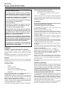
The
front panel will need to be removed in order to change
lamps –see Fig. 10.
Warning - The front panel is heavy and easily damaged.
The
front panel is fixed with 4 spring loaded pins (see ‘a’ in
Fig. 9) and is supported at the top by the chassis.
To gain access to lamps please apply the following
procedure:
While holding the
front panel by its sides with both hands,
carefully pull forwards the panel at the bottom until the pins
detach from the clips - see Fig. 9.
When the bottom holding pins are undone, carefully pull
forwards at the top until the top pins detach and then lift the
front panel up and out (see Fig. 10).
To gain access to the bulbs remove the screws at ‘A’ to remove
the cover bracket ‘X’ - see Fig. 10a.
For access to the bottom bulbs, carefully slide the flexible
rotisserie (see ‘a’ in Fig. 11) to one side ensuring that the
rubber grommet is not lost (see ‘b’ in Fig. 11).
Remove the defective lamp by unscrewing it (see Fig. 11).
Replace with a 60W E14 SES Clear Candle bulb, rotating it.
Take care not to over-tighten the lamp.
Steps for reassembling the heater
1. Refit the rotisserie making sure that the rubber grommet
is carefully pushed into the slotted hole on the axial bracket.
2. Replace the cover bracket ‘X’ - see Fig. 10a.
3. Replace the front by aligning the slots on the front frame
and making sure that it catches fully on the support brackets.