


E-8
English
12
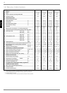
12 Device Information
1 Type and order code
SI 5MER SI 7MER SI 9MER SI 11MER
2Design
2.1 Model Reversible Reversible Reversible Reversible
2.2 Degree of protection according to EN 60 529 IP20 IP20 IP20 IP20
2.3 Installation location Indoors Indoors Indoors Indoors
3 Performance data
3.1 Operating temperature limits:
Heating water flow °C Up to 55 Up to 55 Up to 55 Up to 55
Cooling, flow °C +7 to +20 +7 to +20 +7 to +20 +7 to +20
Brine (heat source, heating) °C -5 to +25 -5 to +25 -5 to +25 -5 to +25
Brine (heat sink, cooling) °C +5 to +25 +5 to +25 +5 to +25 +5 to +25
Antifreeze
Monoethylene
glycol
Monoethylene
glycol
Monoethylene
glycol
Monoethylene
glycol
Minimum brine concentration (-13 °C freezing temperature) 25% 25% 25% 25%
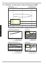
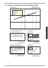
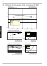
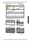
3.2 Temperature spread of heating water (flow/return flow) at B0 / W35K 9.4 9.1 10.6 9.9
3.3 Heat output / COP at B-5 / W55
1
kW / ---
1. This data indicates the size and capacity of the system. For an analysis of the economic and energy efficiency of the system, both the bivalence point and the regulation should
also be taken into consideration. The specified values, e.g. B10 / W55, have the following meaning: Heat source temperature 10 °C and heating water flow temperature 55 °C.
4.0 / 2.0 5.4 / 2.1 7.5 / 2.0 9.8 / 2.1
at B0 / W50
1
kW / ---
4.8 / 2.7 6.2 / 2.7 8.8 / 2.8 11.3 / 2.9
at B0 / W35
1
kW / ---
4.9 / 3.9 6.4 / 3.8 9.3 / 4.0 11.6 / 4.1
3.4 Cooling capacity / COP at B20 / W8 kW / --- 5.4 / 4.6 7.0 / 4.5 9.9 / 4.6 11.4 / 4.6
at B20 / W18 kW / --- 6.6 / 5.3 8.6 / 5.3 12.0 / 5.4 14.1 / 5.3
at B10 / W8 kW / --- 5.4 / 5.6 7.0 / 5.5 9.9 / 5.6 11.6 / 5.7
at B10 / W18 kW / --- 6.8 / 6.7 8.8 / 6.6 12.4 / 6.7 14.1 / 6.5
3.5 Sound power level dB(A) 54 55 56 56
3.6 Heating water flow with an internal pressure differential of m³/h / Pa 0.45 / 1,900 0.6 / 3,300 0.75 / 2,300 1.0 / 4,100
3.7 Brine throughput with an internal pressure differential
(heat source) of m³/h / Pa
1.2 / 16,000 1.7 / 29,500 2.3 / 25,000 3.0 / 24,000
3.8 Refrigerant; total filling weight type / kg R407C / 0.9 R407C / 0.9 R407C / 1.25 R407C / 1.6
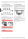
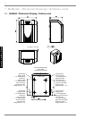
4 Dimensions, connections and weight
4.1 Device dimensions without connections
2
H x W x L mm
2. Note that additional space is required for pipe connections, operation and maintenance.
805 × 650 × 462 805 × 650 × 462 805 × 650 × 462 805 × 650 × 462
4.2 Device connections to heating system Inch G 1¼" external G 1¼" external G 1¼" external G 1¼" external
4.3 Device connections to heat source Inch G 1¼" external G 1¼" external G 1¼" external G 1¼" external
4.4 Weight of the transportable unit(s) incl. packing kg 115 117 124 128
5 Electrical Connection
5.1 Nominal voltage; fuse protection V / A 230 / 16 230 / 16 230 / 20 230 / 25
5.2 Nominal power consumption
1
B0 W35 kW
1.25 1.68 2.3 2.8
5.3 Starting current with soft starter A 24 26 38 38
5.4 Nominal current B0 W35 / cos ϕ A / --- 6.8 / 0.8 9.1 / 0.8 12.5 / 0.8 15.2 / 0.8
6 Complies with the European safety regulations
3
3. See CE declaration of conformity
3 3 3
7 Additional model features
7.1 Water in device protected against freezing
4
4. The heat circulating pump and the heat pump controller must always be ready for operation.
Yes Yes Yes Yes
7.2 Performance levels 1111
7.3 Controller internal/external Internal Internal Internal Internal