


A-I
Anhang · Appendix · Annexes
Anhang / Appendix / Annexes
1 Maßbilder / Dimension Drawings / Schémas cotés................................................................... A-II
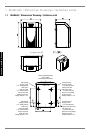
1.1 Maßbild / Dimension Drawing / Schéma coté.........................................................................................A-II
2 Diagramme / Diagrams / Diagrammes....................................................................................... A-III
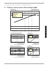
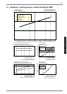
2.1 Heizbetrieb / Heating operation / Mode chauffage SI 5MER.................................................................A-III
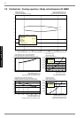
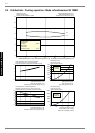
2.2 Kühlbetrieb / Cooling operation / Mode refroidissement SI 5MER ........................................................A-IV
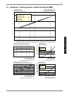
2.3 Heizbetrieb / Heating operation / Mode chauffage SI 7MER..................................................................A-V
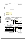
2.4 Kühlbetrieb / Cooling operation / Mode refroidissement SI 7MER ........................................................A-VI
2.5 Heizbetrieb / Heating operation / Mode chauffage SI 9MER................................................................A-VII
2.6 Kühlbetrieb / Cooling operation / Mode refroidissement SI 9MER ......................................................A-VIII
2.7 Heizbetrieb / Heating operation / Mode chauffage SI 11MER...............................................................A-IX
2.8 Kühlbetrieb / Cooling operation / Mode refroidissement SI 11MER .......................................................A-X
3 Stromlaufpläne / Circuit Diagrams / Schémas électriques......................................................A-XI
3.1 Steuerung Standardregler / Control via the standard controller / Commande régulateur standard.......A-XI
3.2 Steuerung Kühlregler / Control via the cooling controller / Commande régulateur refroidissement .....A-XII
3.3 Last / Load / Charge ............................................................................................................................A-XIII
3.4 Anschlussplan Standardregler / Terminal diagram for standard controller / Schéma de branchement du
régulateur standard............................................................................................................................. A-XIV
3.5 Anschlussplan Kühlregler / Terminal diagram for cooling controller / Schéma de branchement du
régulateur de refroidissement.............................................................................................................. A-XV
3.6 Legende / Legend / Légende..............................................................................................................A-XVI
4 Hydraulisches Prinzipschema / Hydraulic Plumbing Diagram / Schéma hydraulique ......A-XVII
4.1 Darstellung / Schematic View / Représentation.................................................................................A-XVII
4.2 Legende / Legend / Légende............................................................................................................A-XVIII
5 Konformitätserklärung / Declaration of Conformity / Déclaration de conformité ...............A-XIX