


8
COMMISSIONING
8
CAUTION!
COMMISSIONING
8.1 General Information
To ensure proper commissioning it should be carried
out by a customer service authorised by the manu-
facturer. Only then can an extended warranty period
of 3 years in total be granted (cf. Warranty service).
8.2 Preparatory Steps
Prior to commissioning, the following items need
to be checked:
- All connections of the heat pump must have
been made as described in Chapter 7.
- The heat source system and the heating circuit
must have been filled and checked.
- The strainer must have been fitted in the sole
inlet of the heat pump.
- In the brine and heating circuits all valves that
might impair the proper flow must be open.
- The settings of the heat pump controller must
be adapted to the heating installation in
accordance with the instructions contained in
the controller's operating manual.
8.3 Commissioning Procedure
The start-up of the heat pump is effected via the
heat pump controller.
Commissioning is to be effected in
accordance with the installation and operating
manual of the heat pump controller.
Where an overflow valve is fitted to assure the
minimum heating water flow rate, the valve must be
set in accordance with the requirements of the
heating installation. An incorrect setting may result
in various error symptoms and an increased elec-
tric power consumption. To correctly set the overflow
valve, the following procedure is recommended:
Close all of the heating circuits which may also be
closed during operation (depending on the type of
heat pump usage) so that the least favourable
operating state - with respect to the water flow rate -
is achieved. Normally, these heating circuits are
those of the rooms located on the south and west
sides of buildings. At least one heating circuit must
remain open (e.g. bathroom).
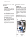
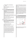
The overflow valve is to be opened to such an extent
that based on the current heat source temperature
the maximum temperature difference between
heating supply and return flow temperature is
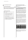
obtained, as indicated in the table below. The
temperature difference should be measured as
closely to the heat pump as possible. In mono-
energetic systems, the electric heating element is
to be deactivated.
Any malfunctions occurring during operation are
displayed on the heat pump controller and can be
corrected as described in the operating manual of
the heat pump controller.
-5 °C 0 °C 10 K
1 °C 5 °C 11 K
6 °C 9 °C 12 K
10 °C 14 °C 13 K
15 °C 20 °C 14 K
21 °C 25 °C 15 K
Heat source temperature
from to
max. difference between heating
supply and return temperature