


7
MOUNTING
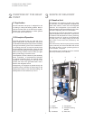
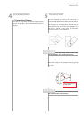
7.3 Connection on Heat Source
Side
The following procedure must be observed when
making the connection:
Connect the brine line to the flow and return pipe
of the heat pump.
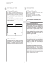
The supplied strainer must be fitted
in the heat source inlet of the heat pump in order
to protect the evaporator against the ingress
of impurities.
In addition, a powerful vent must be installed at
the highest point of the heat source system. The
hydraulic plumbing diagram must be observed
here.
The brine liquid must be produced prior to
charging the system. The brine concentration
must be at least 25 %. Freeze protection down to
-14°C can thus be ensured.
Only antifreeze products on the basis of mono-
ethylene glycol or propylene glycol may be used.
The heat source system must be vented (de-
aerated) and checked for leaks.
The brine solution must contain at
least 25 % of an antifreeze and corrosion
protection agent on a monoethylene glycol or
propylene glycol basis.
7.4 Electrical Connection
The following electrical connections must be
established on the heat pump:
- Connection of the control wire to terminals X1:
L/N/PE in the control box of the heat pump.
- Connection of the load wire to terminals X5:
L1/L2/L3/PE in the control box of the heat pump.
- The control of the brine pump is effected via the
controller N1/J12/N03/N + PE (max. 200 W), or
a pump contactor connected to these terminals
(without PE). If a motor protective switch is used,
the auxiliary contact (NC contact) needs to be
connected to N1/J5/ID5 and X2, instead of the
wire jumper which must be removed.
All electrical components required for the operation
of the heat pump are located in the control box.
CAUTION!
For more detailed instructions concerning the
connection and functioning of the heat pump
controller (e.g. the supplied external wall sensor)
please refer to the enclosed operating manual of
the controller.
An all-pole disconnecting device with a contact gap
of at least 3 mm (e.g. utility company disable contac-
tor or power contactor) as well as a 3-pole circuit
breaker with simultaneous tripping of all external
conductors must be provided . The required cross-
sectional area of the conductors is to be selected
according to the power consumption of the heat
pump, the technical connection requirements of the
relevant utility company and all applicable regula-
tions. Power consumption data of the heat pump is
provided in the product literature and on the
nameplate. The terminals are designed for a max.
conductor cross-section of 35 mm˝.
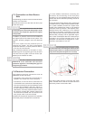
The clockwise phase sequence must
be observed when connecting the load lines (the
heat pump will deliver no output and will be very
noisy when the phase sequence is incorrect).
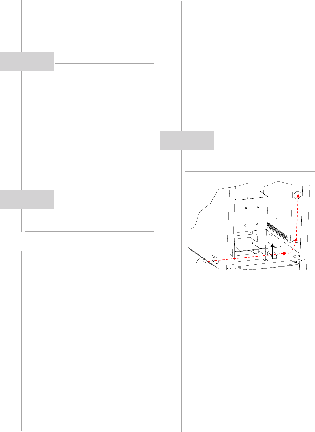
The power cable must be run through the guide
tubes, inserted into the side of the control box and
secured by means of the strain relief.
CAUTION!
CAUTION!