


Operation
The unique flame effect may be enjoyed whether or not the
heating elements are in operation.
Controls
The heater controls are located on the left hand side of the
canopy heat outlet - see Fig. 1.
A switch is in the ON position when the red indicator mark on
the switch is visible.
Setting the Thermostat
Plug in and set all switches to ON. Turn the thermostat knob
to MAX to warm the room rapidly. When the room temperature
has reached the desired level, turn the thermostat knob back
slowly until the thermostat just clicks off. The heater will then
maintain the room temperature at the chosen level.
NOTE – Should your heater fail to come on when the
thermostat is at a low setting, this may be due to the room
temperature being higher than the thermostat setting.
Maintenance
WARNING – BEFORE UNDERTAKING ANY
MAINTENANCE OR CLEANING, REMOVE PLUG OR
DISCONNECT FROM THE ELECTRICITY SUPPLY.
Remote Control
Warning: it takes time for the
receiver to respond to the
transmitter. Do not press the
buttons more than once within
two seconds for correct
operation.
Manual Controls
Note : The Standby
Switch must first be
turned on to operate
either the manual or
the remote controls.
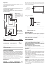
Manual or Remote Operation
To turn off any of the
settings
Press the ‘OFF’ button once
To increase or decrease the brightness of the fuel effect use the
buttons as shown in Fig. 2
Flame effect & 1kW heat Press the ‘ON’ button again
Top & Middle
Neon
Flame effect & 2kW heat Press the ‘ON’ button again
All 3 Neon’s
Setting Operation Indication
Flame effect
Press the ‘ON’ button once
Top Neon
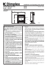
Note: When either the remote control or the manual controls
are used, the neon’s will come on for 3 seconds indicating the
relevant setting (see Fig. 3).
neon’s for
indicating the
operation level
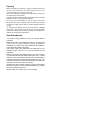
1. Slide open the battery cover on the back of the remote
control
2. Install two AAA batteries into the remote control (see
Fig. 4)
3. Replace the battery cover.
Battery information
Fig. 4
Batteries
Discard leaky batteries
Dispose of batteries in the proper manner according to
Provincial and local regulations. Any battery may leak
electrolyte if mixed with a different battery type, if inserted
incorrectly, if all the batteries are not replaced at the same
time, if disposed of in a fire or if an attempt is made to charge
a battery not intended to be recharged.
ON
OFF
Increase
Brightness
Off
Button
Standby
Switch
Decrease
Brightness
On
Button
Fig. 2
Fig. 3
Lamp Replacement
There are two lamps located beneath the fuel effect.
To gain access to the lamp, the fuel effect which is secured
by three screws, must be removed (see Fig.1).
Remove the coal/pebbles and carefully lift the fuel effect/fuel
effect trim clear and set aside.
Remove the glass shelf and carefully set aside.
Replace the defective lamp with a 240V 60 Watt E14 SES
clear candle lamp.
Replace the glass shelf then the fuel effect assy and secure
with screws.
Safety cut-out
For your safety, this appliance has been fitted with thermal
cut-out. In the event that the product overheats, the cut-out
switches the heat off automatically.
To bring the heat back into operation, remove the cause of
the overheating, then unplug or turn off the electrical supply
to the heater for up to 10 minutes.
When the heater has cooled sufficiently, re-connect and switch
on the heater.
Caution: Inorder to avoid a hazard due to inadvertent
resetting of the thermal cutout, this appliance must not be
supplied through an external switching device, such as a
timer, or connected to a circuit that is regularly switched on
and off by the utility.