


6
MOUNTING
6
MOUNTING
6.1 General
The following connections need to be established
on the heat pump:
- supply/return lines of the heating system
- condensate drain
- control lead to the remote control
- power supply
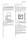
6.2 Heating-Side Connection
The connections on the heating side of the heat
pump are provided with 1"external thread (flat
sealing). When making the connections to the heat
pump, use a wrench to counterhold at the transitions.
Before completing the heat pump connections on
the heating water side, the heating installation must
be flushed in order to remove any impurities that
may be present, as well as any residues of sealing
material, and the like. Any accumulation of deposits
in the condenser may result in a total failure of the
heat pump. On systems equipped with heating water
flow shut-off devices such as radiator or thermostat
valves, an overflow valve, to be provided by the
customer, needs to be installed at the outlet of the
heat pump in a heating system bypass. This assures
a minimum heating water flow through the heat
pump and thus prevents any malfunctions from
occurring.
Once the installation on the heating side has been
completed, the heating system must be filled, de-
aerated and pressure-tested..
Heating water minimum flow rate
The heating water minimum flow rate through the heat
pump must be assured in all operating states of the
heating system. This can be accomplished, for example,
by installing a differential pressure-free manifold or an
overflow valve. The procedure for setting an overflow
valve is described in the Chapter Commissioning.
Frost Protection
On heat pumps installed in a location prone to frost,
a manual drain valve (see "Hydraulic Block Diagrams"
in the Appendix) should be provided. Properly installed
appliances feature an internal frost protection feature.
If the heat pump is taken out of service or in the event
of a power failure, the system must be drained. In
heat pump installations where a power failure cannot
be readily detected (e.g. holiday houses), the heating
circuit must contain a suitable antifreeze product.
6.3 Electrical Connection
The power connection of the heat pump is effected
via a standard 3-core (for 1-phase units) or a 5-core
(for 3-phase units) cable.
In the case of the 1-phase units, an additional 3-core
cable must be installed for the electric back-up heater.
The cable(s) has (have) to be supplied by the client;
the cross-sectional area is to be selected in
accordance with the power consumption of the heat
pump (see Equipment Data in the appendix) as well
as all relevant VDE (EN) and VNB regulations.
The power supply of the heat pump must be equipped
with an all-pole disconnecting device with a contact
gap of at least 3 mm (e.g. utility company shut-off
contactor, power contactor) as well as a 3-pole circuit
breaker, with simultaneous tripping of all external
conductors (tripping current as stated in the Equip-
ment Data).
- optionally, an additional three-core cable is
required for the domestic hot water supply.
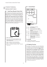
When connecting multiphase units the clockwise
phase sequence of the motor electrical supply must
be assured.
Phase sequence: L1, L2, L3.
Clockwise phase sequence (in the
case of multiphase units) must be ensured: Operating
the compressor in the wrong sense of rotation, may
result in damage to the compressor. An incorrect
phase sequence causes the fan to operate in the
wrong sense of rotation leading to a significant
reduction in performance.
The control voltage for the remote control is provided
by the power supply of the unit.
The connecting lead (control lead) from the remote
control to the heat pump (not included in the scope of
delivery) must be suitable for 230 V mains power
supply. The lead must have (at least) 6 cores and the
cross-section of the single cores must be at least 0.5
mm
2
.
The power supply of the heat pump must be as
specified in the Technical Data of the applicance, i.e.
230 V AC 50 Hz or 3-L/N/PE 400 V.
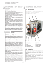
The connection inside the heat pump is to be effected
using the terminal strips in the control box. For
detailed information refer to the Wiring Diagrams in
the Appendix.
CAUTION!