


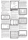
4. FAN SPEED SELECTION - At this point
the installer must choose between Normal/
High Fan or permanent High Fan option.
Option 1 - The heater is factory set at Normal
Fan. The fan will therefore:-
(a) Run at NORMAL when the boost option
is not selected.
(b) Run at NORMAL when the boost is
selected and the core is partially
depleted.
(c) Automatically switch to HIGH when the
boost is selected and the core is almost
fully depleted.
Option 2 - If a High Fan is permanently
required the installer must make the
following adjustment.
(a) Loosen the two screws securing the
wires to the resistor block.
(b) Move the right wire to the left of the block
and tighten both wires in the left
connection point of the resistor block
effectively taking the resistor out of
circuit.
See Fan/Boost Circuit Diagram
5. Ensure that any slack is pulled back
through each clamp and tighten the
clamping screws. Secure cables to base of
heater using ties provided in fixing kit.
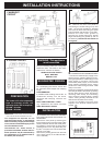
6. Place the heater on its feet, and in the
desired position against the wall - DO NOT
LIFT THE HEATER BY ITS TOP PANEL!
Ensure that the heater is based on a firm
level surface, at least 100mm from any end
wall, and at least 100mm below any shelf
or similar projection. Cut away the gripper
rod or carpet which would prevent the
heater sitting firmly on the floor.
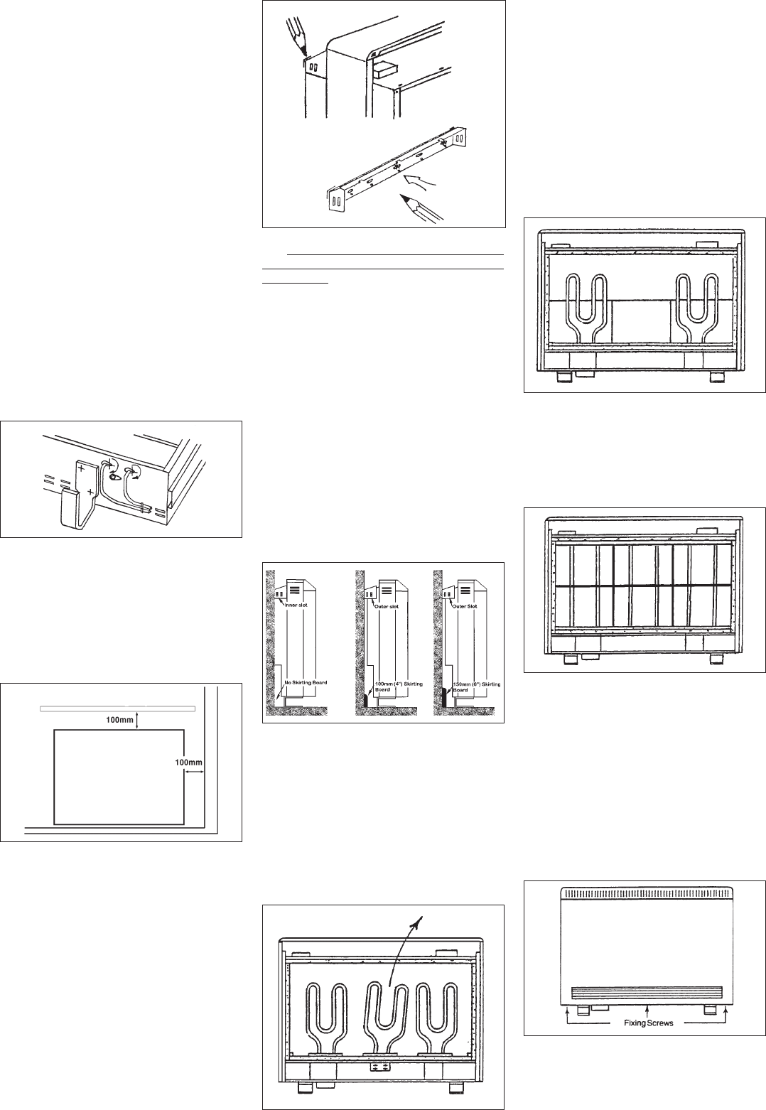
7. Mark the position of the two outside
corners of the wall bracket with the heater
pushed tight against the wall. Remove the
wall bracket from the heater by removing
the screw at each end. Place the heater to
one side and reposition the bracket against
the wall using the corner marks for
alignment.
Four fixing positions must be chosen for
the FXL24N and three for the FXL18N. Mark
the positions for the fixing holes - two at the
extreme ends and others spaced evenly
between them. Remove the bracket from
the wall, drill the holes in the positions
marked, and insert suitable fixings
previously described. Secure the wall
bracket to the wall using the correct
fasteners.
8. THE FOLLOWING MUST BE APPLIED
WHEN FIXING THE HEATER TO THE WALL
BRACKET.
i) If no skirting board is present secure
the heater through the wall bracket slots
closest to the wall.
ii) If 100mm (4 in.) skirting is present
secure the heater through the outer
slots.
iii) If skirting taller that 150mm (6in.) is
present this must be reduced to 150mm
(6 in.) over the entire width of the heater
plus 25mm (1 in.) at each end.
Do not fully tighten these screws until the
bricks are loaded into the heater as some
settling of the heater may occur.
NOTE: NEVER REMOVE THESE SCREWS
WITHOUT FIRST UNLOADING THE
HEATER.
9. Remove one element to allow access
for the back rows of bricks. On the FXL24N
remove the element to the right of centre
and on the FXL18N remove the central
element.
Loosen the two screws securing the
element tails in the ceramic connector
block, and lift the element up and out of the
heater.
10. Carefully fit the bottom row of the
back layer of bricks placing the two end
bricks into position first. Ensure that the
recess in the bricks is toward the rear of
the heater with the narrow end to the
bottom. Repeat this with the top row of
the back layer of bricks but the narrow
end of the recess must be to the top.
Refit the element which had been removed
by feeding the tails down through the hole
in the base insulation and into the connector
block. Ensure the element is fully pushed
home, then securely tighten the two screws
in the block.
11. Fit the front layer of bricks with the
recess toward the front of the heater.
The complete core will comprise:
FXL18N : 3 x 4 brick columns
FXL24N : 4 x 4 brick columns
12. Replace the inner front, complete
with insulation, by locating its bottom edge
behind the front lip of the chassis and
inserting the retaining screws along the top
and sides.
Refit the three inner guards in their
respective locations.
Replace the outer front by hooking the
upper grille into its retaining slot on the top
panel, lower into position and replace the
three self tapping screws along the bottom
edge.
13. Finally, tighten the screws at each
end of the wall bracket. Ensure that all
screws have been tightened as this is
essential to maintain earth continuity.