


INSTALLATION INSTRUCTIONS
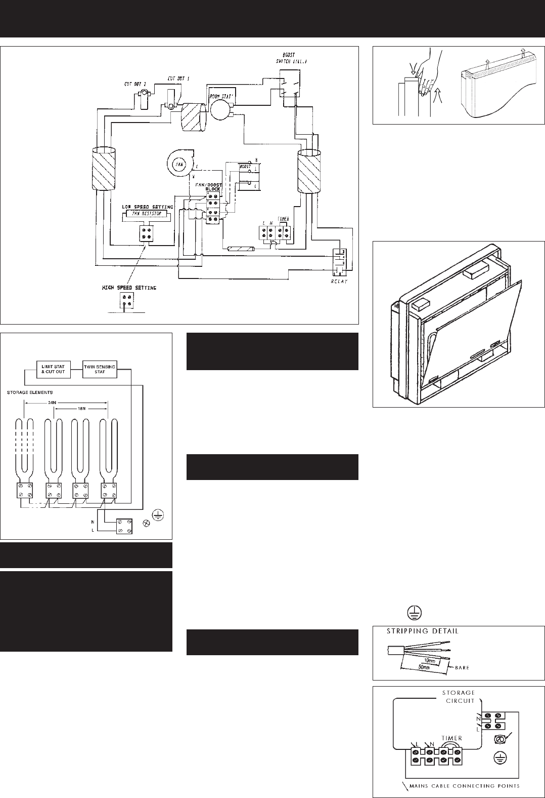
FAN/BOOST
CIRCUIT
STORAGE CIRCUIT
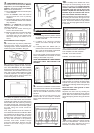
PREPARATION
The heater will arrive separately
from its storage bricks, the
following bricks will be required.
FXL18N - 12 bricks
FXL24N - 16 bricks
Two supplies are required for the
operation of this heater - a restricted Off
Peak or Economy 7 supply for the storage
circuit, and an unrestricted supply for the
fan boost element circuit.
Thermostatic fan / boost control is
provided on the heater, however the fan /
boost operation may be customised by
the introduction of an external timer to
the heater (see section 3).
WARNING - This appliance
must be earthed
Only heat resisting cable (min. rating T85)
should be used. The wires in the mains
cable will be coloured as follows:-
GREEN & YELLOW - EARTH
BLUE - NEUTRAL
BROWN - LIVE
SUGGESTED FIXINGS
SOLID BRICK/BLOCK
No. 10 Rawlplug fibre inserts, 5.5mm drill
bit. Drill hole 10mm deeper than rawlplug
length.
PLASTERBOARD
If possible locate studding and use No. 10
woodscrews directly into the wood,
otherwise M5 rawlplug intersets are
suitable.
NOTE: FOR OTHER WALL TYPES
(e.g. timberframe and hollow concrete)
SEEK SPECIALIST ADVICE.
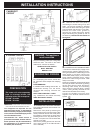
INSTALLATION
1. ENSURE THAT FIXING KIT HAS BEEN
LOCATED BEFORE DISPOSING OF
PACKAGING.
Remove the front panel by removing the
three screws along its bottom edge. With
hands positioned on each side of the panel,
lift upwards to unhook the top edge whilst
pressing down on the top panel with your
thumbs. The panel can now be lifted clear
and set to one side.
Remove the packing pieces from the slots
on the inner front (3 on the FXL18N and 4
on the FXL24N).
2. Remove the inner front panel by
unscrewing the screws along its top and
sides. As the front insulation is attached
care must be taken when lifting this panel
from the heater and placing it to one side.
Remove the three inner guards by
removing the screws along their bottom
edges and sliding the guards up and off
the base tray. Please note the location of
each guard.
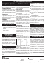
3. CONNECTION OF THE MAINS CABLE
- Connect the restricted (E7) supply to the
terminal block, marked “Storage Circuit”,
having first passed the cable through a front
cable clamp in the base. Connect the
unrestricted (Peak) supply to the terminal
block, marked “Fan/Boost Circuit”, having
passed this cable through another cable
clamp in the base.
At this point, if desired, an external fan/boost
timer may be fitted to the heater by passing
the two wires from the timer through the
remaining cable clamp, and connecting
them across the terminal block, marked
“Timer”, having already removed the link
fitted across this block at the factory.
Connect the EARTH lead from both
supplies to the terminal marked with the
symbol
IMPORTANT DURING NORMAL OPERATION ENSURE
BOTH
SUPPLIES ARE SWITCHED ON AT THE WALL.