


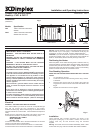
13 : 17
ON
OFF
ADVANCE
AUTO MAN ON OFF
P1
Follow the sequence outlined below when installing the heater.
1. Select the position for the heater ensuring there is
clearance from any furniture and fittings of at least 150mm above
the heater, 230mm below and 75mm each side.
Curtains must not be closer than 150mm from the top of the
heater.
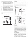
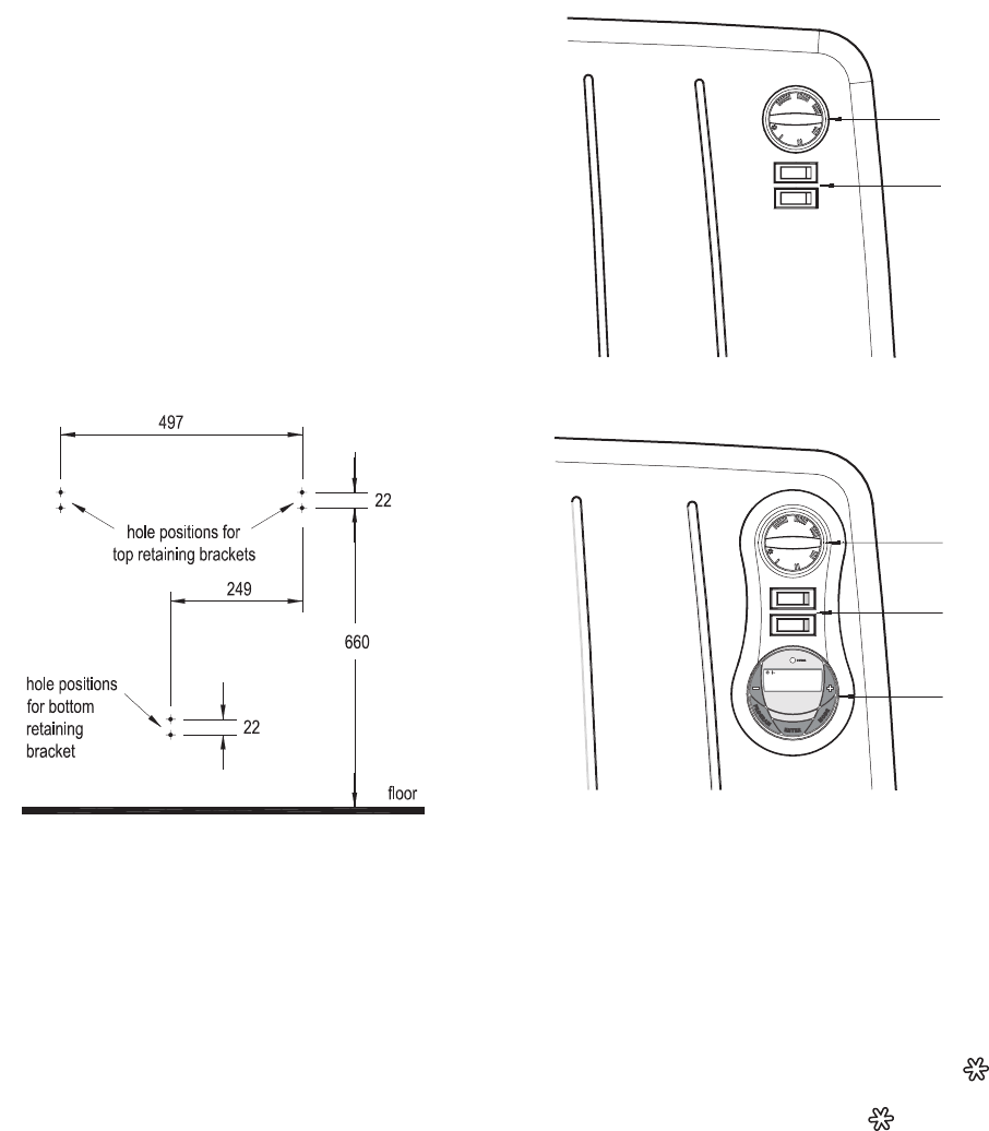
2. Fig. 3 shows the required drill hole positions. Using a straight
edge draw a horizontal line for the top brackets at the required
mounting height from the floor. On this line mark off the fixing
centres at 497mm.
3. Fix the two top retaining brackets to the wall, using
suitable fixings. Ensure that suitable fixings are placed in both
of the fixing holes provided in each bracket.
4. Locate the heater on the top brackets and allow it to hang in
place.
5. Fit the bottom bracket into the slot in the heater and then let it
rest against the wall. Mark the hole positions.
6. Remove the heater and drill and plug the holes for the bottom
bracket.
7. Re-hang the heater with the bottom bracket fitted to the heater
and screw fix the bracket to the wall.
Test that the heater is now securely fixed to the wall.
Note: We recommend that the heater should be wall mounted in rooms
where children may be left unattended. See also ‘Important Safety
Advice’.
Operation
Important – Objects or clothing must not be placed on this heater.
Before using the heater ensure that all warnings and
instructions have been read carefully.
Fig. 3
When you have completed the installation, plug in and switch on the
power. Two switches on the front panel of the heater control the heat
output.
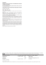
Both switches illuminated indicate both the the front and back panels
are in operation and the heater is operating at maximum output (1kW) -
see Fig. 4A for CVP1 heater controls and Fig. 4B for CVP1T heater
controls.
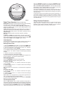
Fig. 4B
Thermostat
Controls
Thermostat
The Thermostat controls the heat output according to the room
temperature. This ensures that the heater will not produce heat
unnecessarily when the room is warm. To set the temperature you
require, turn the thermostat knob clockwise until the required setting is
reached. Alternatively to heat a cold room quickly, turn the thermostat
knob up fully. When the room has reached the desired temperature,
turn the thermostat knob anti-clockwise until the thermostat just clicks
off. The heater will now automatically operate at this temperature. The
thermostat also has a frost protection setting marked ‘ ‘. This setting
is useful in areas such as garages, to prevent frost damage. If the
thermostat is set to its minimum setting ‘ ’, the heater will cycle on
and off to maintain a temperature of approximately 5° to help protect
against frost.
Heat Selector Switches
Top Switch - The top switch controls the back panel element. When
this switch is illuminated this indicates that the 450W oil panel element
is on.
Bottom Switch - The lower switch is used to control the front panel
element. When the lower switch is illuminated this
indicates that the 550W front panel element is on.
Timer (CVP1T model only)
Note: At least one switch must be in the ‘On’ position for the heater to
operate. - see ‘Digital Timer Operation’.
Heat Selector
Switches
Timer
Thermostat
Heat Selector
Switches
Fig. 4A