shelf
Dimplex Dual Warmth Heater
Model(s): CVP1 & CVP1T
Installation and Operating Instructions
INDUKCVPRG Issue 2
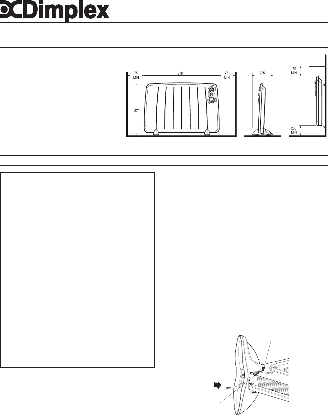
Dimensions
(millimetres)
THESE INSTRUCTIONS SHOULD BE READ CAREFULLY AND RETAINED FOR FUTURE REFERENCE
Specification
1000W Thermostat / 2 Neon Heat
Switches
1000W Thermostat / 2 Neon Heat
Switches & 24 Hour Timer
Models
CVP1
CVP1T
Fig. 1
Fig. 2
hook
recess
Installation
Three identical wall mounting brackets are stored in the
polystyrene packaging of the heater. Please note that the
radiator must only be wall mounted using the brackets
supplied.
Warning: This heater must not be located immediately below a fixed
socket outlet. The plug must be accessible after heater installation.
floor
mounted
wall
mounted
CVP1T shown
IMPORTANT SAFETY ADVICE
WARNING - THIS APPLIANCE MUST NOT BE USED IN A
BATHROOM
WARNING – DO NOT USE THIS HEATER IN THE IMMEDIATE
SURROUNDINGS OF A BATH, A SHOWER OR A SWIMMING
POOL
WARNING – THIS HEATER MUST NOT BE LOCATED
IMMEDIATELY BELOW A FIXED SOCKET OUTLET.
DO NOT USE THE HEATER UNTIL THE FEET OR WALL
BRACKETS ARE FITTED CORRECTLY.
FOLLOW these instructions carefully.
The heater carries a warning ‘DO NOT COVER’ to alert the user
to the risk of fire that exists if the heater is accidentally covered.
This appliance is not intended for use by children or other
persons without assistance or supervision if their physical,
sensory or mental capabilities prevent them from using it safely.
Children should be supervised to ensure that they do not play
with the appliance.
We recommend a guard be fitted to ensure contact with the
heater is avoided and objects cannot be inserted in to the
product.
If the mains lead is damaged, it must be replaced by the
manufacturer or its service agent or a similarly qualified person
in order to avoid a hazard.
For further information, please contact our guard supplier direct
on Tel. No. 01603 667957, or in case of difficulty or for further
advice contact the Customer Helpline - (details on back page)
Electrical
WARNING – THIS APPLIANCE MUST BE EARTHED
If the socket outlets in your home are not of the 13 amp BS1363 type
they will not accept the plug connected to this heater,
therefore cut off the plug. When cut off this plug can constitute a shock
hazard if inserted into a socket outlet. It must therefore be disposed of
safely.
Before wiring the appropriate plug please note that the wires in this
mains lead are coloured in accordance with the following code:
GREEN/YELLOW - EARTH
BLUE - NEUTRAL
BROWN - LIVE
Connect the Green/Yellow wire to the terminal marked E or the earth
symbol or coloured Green or Green/Yellow.
Connect the Brown wire to the terminal marked L or coloured Red.
Connect the Blue wire to the terminal marked N or coloured Black.
DO NOT connect the Brown (Live) or the Blue (Neutral) wires to the
Earth terminal of your 13 amp plug. If the terminals of the plug are
unmarked or you are in any doubt, consult a qualified electrician.
CAUTION: If you use this heater in conjunction with a thermal control,
programme controller, timer or any other device which switches the
heater on automatically observe all safety warnings at all times.
Positioning the Heater
Select the position for the heater ensuring there is clearance from any
furniture and fittings of at least 150mm above the heater, 230mm below
(wall mounted) and 75mm each side - see Fig. 1. Curtains must not be
closer than 150mm from the top of the heater. If used in a free-standing
position the heater should be on a flat stable surface.
Free Standing Operation
NEVER USE THE HEATER FREE STANDING WITHOUT THE FEET
FITTED.
1. Lay the heater on it’s front.
2. Locate and remove the two foot fixing screws using a X-head
screwdriver.
3. Place the feet over the base of the heater, align holes and
engage hook on foot into recess on the back of the heater - see
Fig. 2.
4. Replace the screws but do not over tighten.


