


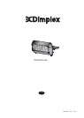
Dimplex CXD Ceramic Radiant Heater
Model(s) : CXD2000H-NA
Important Safety Advice
Because the Dimplex Ceramic Radiant Heater contains no
moving parts little maintenance is required. Before
undertaking any maintenance work on the heater due
attention must be paid to the following:
This heater is designed to be horizontally wall mounted
only, it must not be ceiling mounted.
Always ensure a safe mounting height, at or above a
minimum height of 1.8 metres from ground level, so that
the heater can not be touched when in operation.
The heater must be wall mounted level ± 5º to the
horizontal.
Do not locate the heater immediately above or below a
fixed socket outlet or connection box.
Always disconnect the heater from the electricity supply
before attempting to work on or near it.
Always ensure a safe means of access using an access
tower or properly supported ladder.
Do not cover the heater.
Keep combustible materials away from the heater.
Do not position patio furniture, sunshades, awnings and
other combustible materials too close to the heater.
Do not use heater if the elements are broken - as injury
may occur.
Allow adequate time (minimum of 30 mins.) for the
elements and body casing to cool before attempting to
work on the heater .
Wiring between the heater and the spur outlet or isolation
switch must be in a heat resisting cable (e.g.
polychloroprene).
Do not install less than 1.8 metres (6 feet) from ground
level.
Warning: Please ensure all packaging is removed from
the appliance before switching on.
General
Your Dimplex Ceramic Radiant Heater uses ceramic elements which
produce a high proportion of their output in the long-wave infra-red.
This provides a high comfort factor – similar to the natural energy
from the sun.
Electrical
The installation of this appliance should be carried out by a
competent electrician and be in accordance with the current
IEE wiring regulations and any local or insurance regulations.
The CXD2000H-NA is designed for use on a 230-240V AC single
phase supply.
An all-pole isolating switch with a minimum separation of 3mm in
each pole must be fitted to facilitate isolation. This switch must either
be positioned inside a building or have an IP rating against water
ingress suitable for external installation.
The appliance must be supplied through a residual current device
(RCD) having a rated residual operating current not exceeding 30mA.
The appliance must be connected to a socket-outlet having an earthing
contact.
We recommend that a cable with a minimum specification of H07RN-
F polychloroprene sheathed or similar be used with a minimum
temperature rating of 90°C.
The wiring to the appliance must be connected with a UL approved
watertight connection for outdoor use. Remove rain shield for access
to this connection and then replace rain shield once connection is
completed. Appliance must have rain shield installed at all times during
operation.
Note : Always ensure the cable grip is tightened.
THESE INSTRUCTIONS SHOULD BE READ CAREFULLY AND RETAINED FOR FUTURE REFERENCE
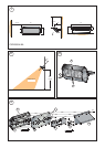
Installation
Heaters are supplied with an integral wall bracket which may be
fixed through the mounting holes to any suitable structure. The bracket
positions the heater at the an angle of 45 degrees for optimum
performance. The recommended fixing height is 1.8m from ground
level - see Fig. 2.
The integral wall fixing bracket may be removed by fully unscrewing
to facilitate its fixing.
The siting of the heater(s) should be such as to allow an even and
uninterrupted distribution of radiation to the area(s) to be heated.
When deciding upon the best location, consideration must be given
to the following requirements:
a. Avoid structures which might vibrate e.g. crane gantries.
These could adversely affect element life.
b. Comfort and safety could be compromised unless the heater is
mounted at or above 1.8m from ground level.
c. Allow a minimum of 500mm minimum clearance between the
top of the heater and any horizontal surface - see Fig. 1.
Element Replacement (see Fig. 4)
WARNING – BEFORE UNDERTAKING THIS TASK ENSURE THE
HEATER IS DISCONNECTED FROM THE ELECRICITY SUPPLY AND
LEFT TO COOL FOR A MINIMUM OF 30 MINUTES.
1. The heater should be taken off the wall.
2. Remove 3 screws to remove the rain shield (see ‘a’ in Fig. 4) to
gain access to the control box on the back of the heater.
3. Remove 4 screws to remove the terminal block plate (see ‘b’ in
Fig. 4) and disconnect the terminal block.
4. Remove 8 screws to remove the control box (see ‘c’ in Fig. 4).
5. This will allow access to the elements. Remove the retaining
clips and spring clips (f) to loosen the elements.
6. Disconnect the elements from their terminal blocks.
7. Remove the remaining 5 screws which hold the back panel (see
‘d’ in Fig. 4).
8. Remove the splash brackets (see ‘g’ in Fig. 4) on the elements.
9. Bend the bars on the guard as indicated in Fig. 3 to remove it.
10. The old element should drop out through the front of the heater,
reverse the process when replacing with the new element -
Element Replacement Kit No. - FTELLN-1-KIT (Optional).
Cleaning and User Maintenance
WARNING: BEFORE UNDERTAKING CLEANING OR MAINTENANCE
WORK ON THE APPLIANCE, DISCONNECT THE ELECTRICITY
SUPPLY.
Since the appliance contains no moving parts little maintenance is
required beyond cleaning and element replacement. It is however
essential that the heater is not operated with an accumulation of
dust or dirt on the element, as this can cause a build up of heat and
eventual damage. For this reason the heater must be inspected
regularly, depending upon conditions and at least at yearly intervals.
Allow adequate time for the element and body casing to cool before
attempting to work on the heater - a minimum time of 30 minutes is
recommended.