


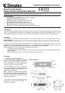
2. Power supply connection
Check that the supply voltage details on the heater are in accordance with your electricity supply. The appliance is fitted
with 2 metres of flexible cable type H05VV-F size 3 x 1.5mm for electrical connection. The cable may be used to
connect the heater to the fixed wiring of the premises through a suitable connection box. The supply circuit to the heater
must incorporate a double pole isolating switch having a contact separation of at least 3mm. The power supply cable
should be routed from the plinth space to the connection box, ensuring that the cable is left with enough slack to allow
removal of the appliance for maintenance. The cable must be protected from any sharp edges.
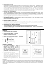
3. Fitting the Rear Support Bracket
The heater is supplied with a rear support bracket. Fit to the back of the appliance with the two screws supplied. Adjust
the rear support bracket so that the vertical distance from the underside of the appliance to bottom of the rear support
bracket equals the vertical distance from the floor in the cupboard space to the bottom of the aperture opening. The
slots in the rear support bracket allow it to be adjusted to the required height.
4. Marking the Fixing Positions
Slide the heater into position in the plinth aperture. Mark the six fixing holes (two on each side and two on the top
Remove the heater and drill 2mm pilot holes.
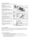
5. Mounting the Heater into the Plinth
When the cable connection has been made and the rear support bracket adjusted, slide the heater into the aperture
ensuring that it is adequately supported and that the inlet grille is not obstructed. Use the six screws provided to secure
the heater to the plinth. (See point 6 below for stainless steel grill fitting).
6. Stainless Steel Grille (BFH24TS model only).
The stainless steel grille is supplied (in the plastic covering) as an attachment for the front of the heater.
This should be offered up to the front of the heater before fixing the heater to the plinth. Use the six screws to secure it
to the front of the heater / plinth.
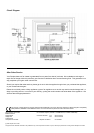
Operation
1 Switch on electricity supply to the heater.
2 Switching the switch marked “ l “energises
blower and illuminates neon indicator.
3 Select " l " and switches marked "
● " and “ “ as required:
1 + + = Cooling
1 +
● + = 800W heating
●
●
1 + + = 1600W heating
1 +
● + = 2400W heating
●
●
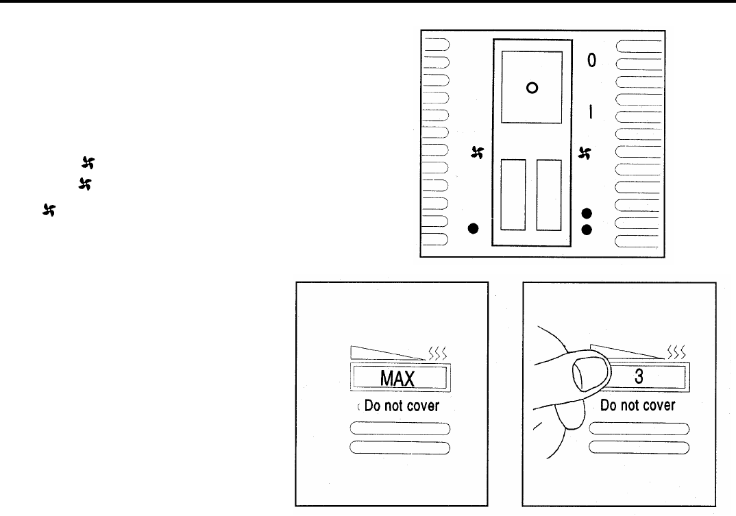
Operation of Thermostat
1.
The heater incorporates a variable
thermostat which is controlled by a knob
situated on the top right hand side of the
front panel. The knob is marked *, 1 - 6,
MAX, representing a temperature range of
5°C to 30°C. Lowest setting provides frost
protection level.
2. Turn thermostat knob to maximum.
When the room has reached the desired
comfort level turn back the knob until the
thermostat just ' clicks ' off. If the knob is left
in this position the room temperature will be
maintained automatically at the chosen level.
Remember
If, when the heater is switched on, the room temperature is above that selected on the thermostat knob the heater will not
operate. This is as it should be, and the thermostat is performing its function correctly. Should a higher temperature be
required than the one selected, then it will be necessary to turn the thermostat knob to a higher setting to bring the heater
into operation.