


www.dimplex.de E-7
English
8.1
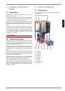
7 Start-up
7.1 General Information
To ensure that start-up is performed correctly, it should only be
carried out by an after-sales service technician authorized by the
manufacturer. This may be a condition for extending the guaran-
tee (see Warranty Service).
7.2 Preparation
The following items need to be checked prior to start-up:
All of the heat pump connections must be established as de-
scribed in Chapter 6.
All valves that could impair the proper flow of the heating
water in the heating circuit must be open.
The air intake and air outlet paths must not be blocked in any
way.
The ventilator must turn in the direction indicated by the ar-
row.
The settings of the heat pump controller must be adapted to
the heating system in accordance with the controller’s oper-
ating instructions.
The condensate outflow must not be impaired.
7.3 Procedure
The heat pump is started up via the heat pump controller. Adjust-
ments should be made in compliance with the instructions.
If an overflow valve is fitted to maintain the minimum heating
water flow rate, the valve must be adapted to the requirements of
the heating system. Incorrect adjustment can lead to faulty oper-
ation and increased energy consumption. We recommend carry-
ing out the following procedure to correctly adjust the overflow
valve:
Close all of the heating circuits that may also be closed during
operation (depending on the type of heat pump usage) so that
the most unfavourable operating state - with respect to the water
flow rate - is achieved. This normally means the heating circuits
of the rooms on the south and west sides of the building. At least
one heating circuit must remain open (e.g. bathroom).
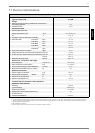
The overflow valve should be opened far enough to produce the
maximum temperature spread between the heating flow and re-
turn flow listed in the following table for the current heat source
temperature. The temperature spread should be measured as
close as possible to the heat pump. The heating element of mono
energy systems should be disconnected.
Any faults occurring during operation are also displayed on the
heat pump controller and can be corrected as described in the
operating instructions of the heat pump controller.
For external temperatures below 10 °C and heating water tem-
peratures below 16 °C, the buffer tank should be heated up with
the 2nd heat generator to at least 25 °C.
Observe the following procedure to implement a smooth start-up:
1) Close all of the heating circuits.
2) Fully open the overflow valve.
3) Use the controller to select the automatic operating mode.
4) Wait until the buffer tank has reached a temperature of at
least 25 °C.
5) Now slowly reopen the heating circuit valves in succession
so that the heating water throughput is constantly raised by
slightly opening the respective heating circuit. The heating
water temperature in the buffer tank must not be allowed to
drop below 20 °C during this process. This ensures that the
heat pump can be defrosted at any time.
6) Set the minimum volume flow quantity on the overflow valve
and heat circulating pump when all heating circuits are fully
open and a heating water temperature in the buffer tank of
approx. 20 °C is maintained.
7) New buildings have an increased heat consumption on ac-
count of the energy required to dry them out. This increased
heat consumption means that marginally dimensioned heat-
ing systems can not always achieve the desired room tem-
perature. In such cases, we recommend keeping a 2nd heat
generator on standby during the first heating period. The
limit temperature on the heat pump controller should also be
turned up to 15 °C.
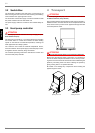
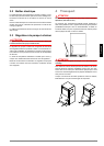
8 Maintenance and
Cleaning
8.1 Maintenance
Avoid leaning or putting objects on the device in order to protect
the paintwork. The external parts of the heat pump can be wiped
with a damp cloth and domestic cleaner.
ATTENTION!
Never use cleaning agents containing sand, soda, acid or chloride
because these could damage surfaces.
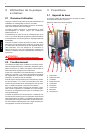
To prevent faults due to sediment in the heat exchanger of the
heat pump, ensure that the heat exchanger in the heating system
can not be contaminated. We recommend protecting the evapo-
rator by installing a bird guard in the inlet duct. At least 80 % of
the cross section of the grating should be open. In the event that
operating malfunctions due to contamination occur nevertheless,
the system should be cleaned as described below.
Heat source
temperature
Max. temperature spread
between heating flow and return
flow
From To
-20 °C -15 °C 4 K
-14 °C -10 °C 5 K
-9 °C -5 °C 6 K
-4 °C 0 °C 7 K
1 °C 5 °C 8 K
6 °C 10 °C 9 K
11 °C 15 °C 10 K
16 °C 20 °C 11 K
21 °C 25 °C 12 K
26 °C 30 °C 13 K
31 °C 35 °C 14 K