


www.dimplex.de E-5
English
6.2
5 Installation
5.1 General Information
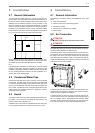
The unit must be installed indoors on a level, smooth and hori-
zontal surface. The entire base of the frame should lie directly on
the floor to ensure a good soundproof seal. If this is not the case,
additional sound insulation measures may be necessary. If the
device is installed on top of a built-under buffer tank, a surface
that fully supports the base is required. The heat pump must be
installed so that maintenance work can be carried out without
being hindered. This can be ensured by maintaining a clearance
of 1 m in front and to the left and right of the heat pump.
Never install the device in rooms subject to high humidity. Con-
densation can form on the heat pump and air circuit if the humid-
ity exceeds 50 % and the external temperature is below
O °C.
If the heat pump is installed on an upper storey, the load-bearing
capacity of the ceiling should be checked. On account of the
acoustics, measures for isolating possible vibrations should also
be very carefully planned in advance as well. Installation on a
wooden floor is not recommended.
5.2 Condensed Water Pipe
Condensed water that forms during operation must be drained
off frost free. The heat pump must be mounted on a level plane
to guarantee proper drainage. The condensed water pipe must
have a minimum diameter of 50 mm and should be fed frost-free
into a sewer. Condensate should not be discharged directly into
clearing tanks and cesspits because the aggressive vapours
could destroy the evaporator.
5.3 Sound
To prevent solid-borne sound from being transmitted to the heat-
ing system, we recommend connecting the heat pump to the
heating system using a flexible hose.
Installed air ducts should be sound-isolated from the heat pump
to prevent the transmission of solid-borne sound to the ducts.
6 Installation
6.1 General Information
The following connections need to be established on the heat
pump:
Fresh and exhaust air
Flow and return flow of the heating system
Condensate outflow
Control line to the heat pump controller
Power supply
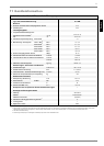
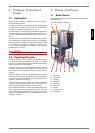
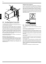
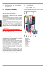
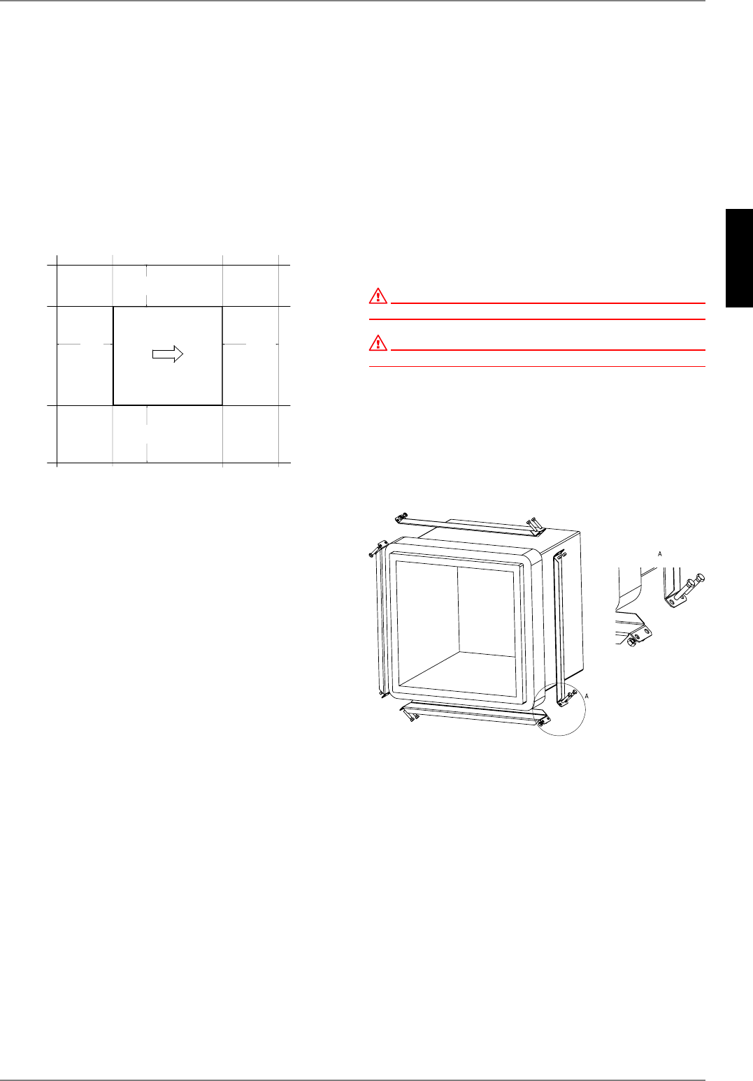
6.2 Air Connection
ATTENTION!
Do not restrict or block up the area around the air inlet or outlet.
ATTENTION!
Only operate the heat pump with the air ducts connected.
The glass fibre reinforced concrete air ducts offered as accesso-
ries are moisture-resistant and diffusion-free.
The sealing collar is used to seal the air ducts on the heat pump.
The air ducts are not screwed directly onto the heat pump. Only
the rubber seal comes into direct contact with the heat pump
when the system is installed correctly. This guarantees easy as-
sembly and disassembly of the heat pump and also ensures that
solid-borne sound is well insulated.
If another type of air duct is used, observe the external and inter-
nal dimensions as specified in the figure. Also ensure that the vi-
bration and duct insulation are adequate.
If flange-mounted air ducts are used, connecting stubs are se-
cured on the air inlet and air outlet sides of the evaporator with 4
M8 x 16 hexagon bolts in the threaded holes provided. When
doing this, ensure that both air duct stubs only touch the insula-
tion. There should be no contact with the external sheeting.
P
P
P
P