


www.desatech.com
114370-01E 9
INSTALLATION
Continued
4. Place log set assembly in center of
fireplace floor. Make sure front faces
forward.
5. Install gas connector tube into gas supply
tting. Carefully shape tube to attach to
adapter tting being careful not to kink
tube.
6. Install provided gas connector tube
into the gas inlet fitting (see Figure 7,
page 8).
7. Test for leaks following instructions under
Testing Burner for Leaks.
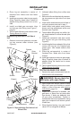
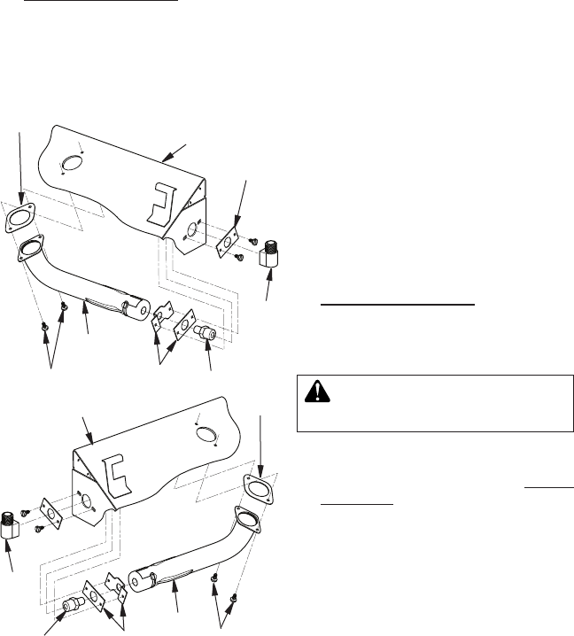
Unit
1. Remove venturi and gasket by unscrew-
ing two screws under chassis (see
Figure 8).
2. Unthread elbow tting from orice (see
Figure 8).
3. Remove orice and brackets by unscrew-
ing two screws on right side of unit (see
Figure 8).
4. Install orice and brackets into left side of
unit using screws removed in step 1.
5. Install venturi and gasket under bottom
burner and into repositioned orice and
brackets (see Figure 8).
6. Thread elbow tting back into orice. Ap-
ply thread sealant to orice threads (see
Figure 8).
7. Install gas connector tube that comes
with log set into gas inlet tting (see
Figure 8).
8. Install supplied brass adapter tting that
comes with log set into replace gas
supply pipe. Use thread sealant (see
Figure 8).
9. Place log set assembly in center of
fireplace floor. Make sure front faces
forward.
10. Install gas connector tube into gas supply
tting. Carefully shape tube to attach to
adapter tting. Be careful not to cause
kinks in tube.
11. Test for leaks following instructions under
Testing Burner for Leaks.
TESTING BURNER FOR LEAKS
1. Generously apply noncorrosive leak de-
tection uid to all connections.
WARNING: Never check for
2. Light burner with shutoff valve no more
than half open and holding a match
slightly in front of the pan (see Lighting
Instructions, page 10).
3. Inspect all connections for bubbles, raw
gas odors, or ame from any area other
than burner. If leaks are detected, shut
off gas valve immediately. Tighten or
reassemble the loose connections using
pipe joint compound until burner system
is leak free.
4. When nished testing, turn gas shutoff
valve OFF to extinguish all ames.
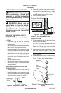
Figure 8 - Repositioning Gas Inlet to Left
Side of Unit
Outer
Bracket
Gasket
Venturi
Screws
Inner
Brackets
Orice
Elbow
Fitting
Elbow
Fitting
Inner Brackets
Orice
Gasket
Venturi
Screws
Chassis
Chassis