


www.desatech.com
114370-01E8
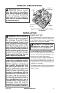
INSTALLATION
Continued
CHECKING GAS CONNECTIONS
and connections, internal and
external to unit, for leaks after
WARNING: Never use an
-
PRESSURE TESTING GAS SUPPLY
PIPING SYSTEM
Test Pressures In Excess Of 1/2 PSIG
1. Disconnect log set with its individual
equipment shutoff valve from gas supply
piping system.
2. Cap off open end of gas pipe where equip-
ment shutoff valve was connected.
3. Pressurize supply piping system by either
using compressed air or opening main gas
valve located on or near gas meter.
4. Check all joints of gas supply piping sys-
tem. Apply noncorrosive leak detection
uid to gas joints. Bubbles forming show
a leak.
5. Correct all leaks at once.
6. Reconnect log set and equipment shutoff
valve to gas supply. Check reconnected
ttings for leaks.
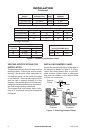
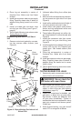
1. Close equipment shutoff valve (see Fig-
ure 5).
2. Pressurize supply piping system by either
using compressed air or opening main gas
valve located on or near gas meter.
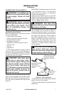
Figure 6 - Checking Gas Joints
HEARTH KIT ASSEMBLY AND
INSTALLATION
1. Determine which side the gas line will be
coming into the replace.
NOTICE: Unit comes preassembled with
gas inlet on right side. If your replace gas
supply is on the left, gas inlet should be
repositioned to left side of unit.
2. If gas supply line in your replace is on the
right side, continue to step 3. If not, see
Repositioning the Gas Inlet to the Left Side
of Unit, page 9.
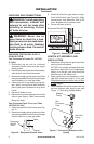
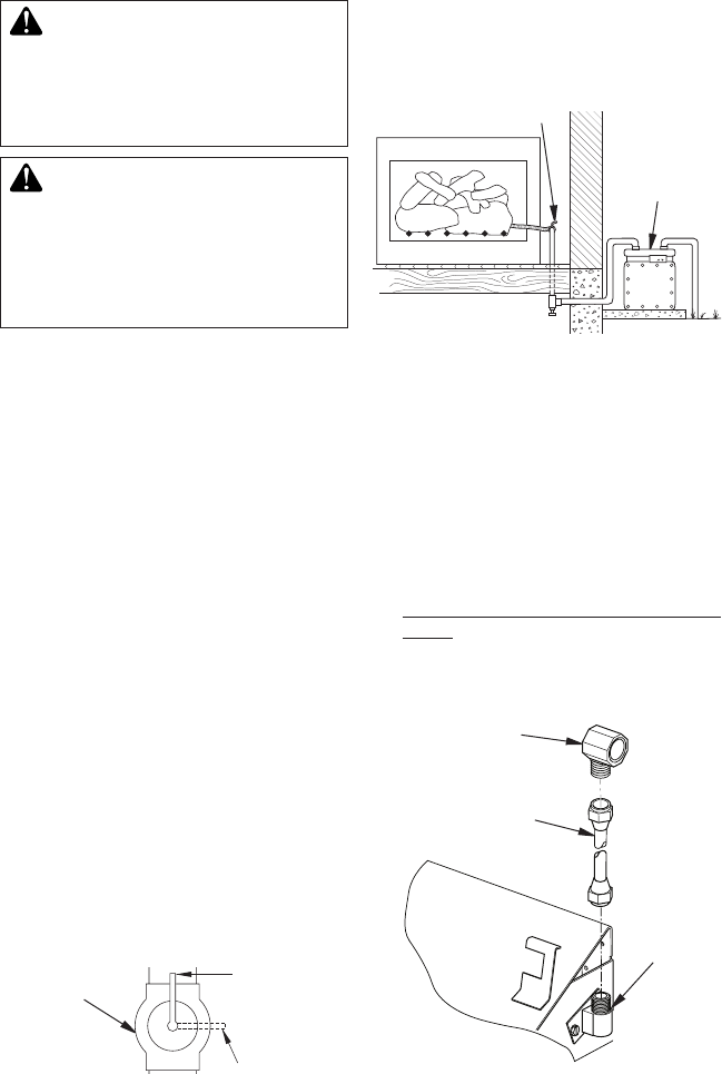
3. Install adapter tting that comes with log
set into replace gas supply pipe (see
Figure 7). Seal using thread sealant.
Figure 7 - Connecting Adapter to Gas
Supply
Gas
Connector
Tube
Adapter
Fitting
Gas Inlet
Fitting
Equipment Shutoff Valve
Gas Meter
Figure 5 - Equipment Shutoff Valve
Equipment
Shutoff
Valve
Open
Closed
3. Check all joints from gas meter to equip-
ment shutoff valve (see Figure 6). Apply
noncorrosive leak detection uid to all
joints. Bubbles forming show a leak.
4. Correct all leaks at once.