


122026-01
Rev. A
06/07
DESA Heating, LLC
2701 Industrial Drive
P.O. Box 90004
Bowling Green, KY 42102-9004
www.desatech.com
GAS FIREPLACE INSTALLATION
1. Fireplace should be fully assembled. See Assembling
Fireplace in replace owner’s manual.
2. Place mantel base close to installation location. See re-
place owner’s manual for installation clearances. Leave
enough room to insert replace from back of mantel.
3. Install gas line. See Connecting to Gas Supply in replace
owner’s manual. Remember to leave access to the gas
shutoff valve somewhere on the base or where it is ac-
cessible to the user.
4. Check for leaks. See Checking Gas Connections in re-
place owner’s manual.
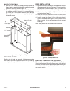
5. Position replace inside mantel (see Figure 6). Carefully
position gas lines. Important: Use caution when position-
ing replace on base. Base may scratch easily. Make
sure replace is in proper position within mantel opening
before continuing with installation.
6. Fireplace with louver door: Lower bottom louver door.
Use two screws provided in hardware package and attach
replace to wooden base. Close louver door.
Figure 6 - Installing Fireplace
Fireplace with xed louver: Before installing logs or
burner assembly (see owner’s manual) remove screws
securing oor to assembly. Lift oor for access to bot-
tom of replace. Use two screws provided in replace
hardware package and attach replace base to wooden
base. Reinstall oor with screws removed previously.
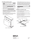
7. If mantel trim has not yet been assembled, see As-
sembling Perimeter Trim. Place metal trim on shoulder
screws. Firmly snap trim assembly over shoulder screws
on replace.
8. Carefully push mantel and base into position against
wall.
ASSEMBLING PERIMETER TRIM
1. Remove packaging from three pieces of metal trim.
2. Locate two adjusting plates with set screws, and two
shims in the hardware packet.
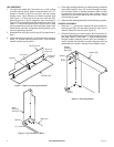
3. Align shim under adjusting plate as shown in Figure 7.
4. Slide one end of adjusting plate/shim in slot on mitered
edge of top trim (see Figure 7).
5. Slide other end of adjusting plate/shim in slot on mitered
edge of side trim (see Figure 7).
6. While rmly holding edges of trim together, tighten both
set screws on the adjusting plate with slotted screw-
driver.
7. Repeat steps 2 through 6 for other corner.
Figure 7 - Assembling Trim
Side Trim
Slot
Top Trim
Mitered Edge
Shim
Set Screws
Adjusting
Plate
Slot