


www.desatech.com
119494-01C
3
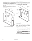
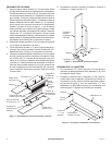
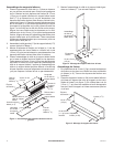
Figure 4 - Installing Header Assembly
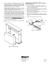
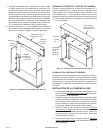
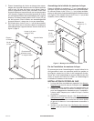
Figure 5 - Attaching Mantel Top
1/2" Screw
Bracket
Threaded
Insert
Shoulder of
Leg Front
Panel
Header (#6) with
Extension (#6A)
1
1
/
4
"
Screw
Washer
Mantel Top
(#7)
Mantel Side
Assembly
3. Place header assembly into position on top of leg as-
semblies with arrow pointing up. Bottom of header will
slide in behind upper portion of leg front panels and rest
on shoulders (see Figure 4). Align bracket holes with
threaded inserts in leg assemblies. Using four 1/2" screws
through brackets, attach header to leg assemblies. Leave
screws loose.
4. Using two 1
1
/
4
" screws with washers, attach header
extension to leg assemblies as shown in Figure 3, page
2, but do not tighten.
MANTEL TOP ASSEMBLY
Place mantel top (#7) on mantel assembly. Align back of top
with back of sides. Using four 1
1
/
4
" screws with washers, place
two in each mantel side assembly (see Figure 5). Using three
1
1
/
4
" screws with washers, attach top to header.
FINISHING MANTEL
Starting with left side leg assembly and with one person
holding parts in alignment, tighten screws using Allen wrench
provided. Tighten screws on the right side leg assembly,
header extension, header, top assembly and base.
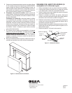
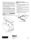
GAS FIREPLACE INSTALLATION
1. Fireplace should be fully assembled. See Assembling
Fireplace in replace owner’s manual.
2. Place mantel base close to installation location. See re-
place owner’s manual for installation clearances. Leave
enough room to insert replace from back of mantel.
3. Install gas line. See Connecting to Gas Supply in replace
owner’s manual. Remember to leave access to the gas
shutoff valve somewhere on the base or where it is ac-
cessible to the user.
4. Check for leaks. See Checking Gas Connections in re-
place owner’s manual.