


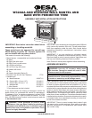
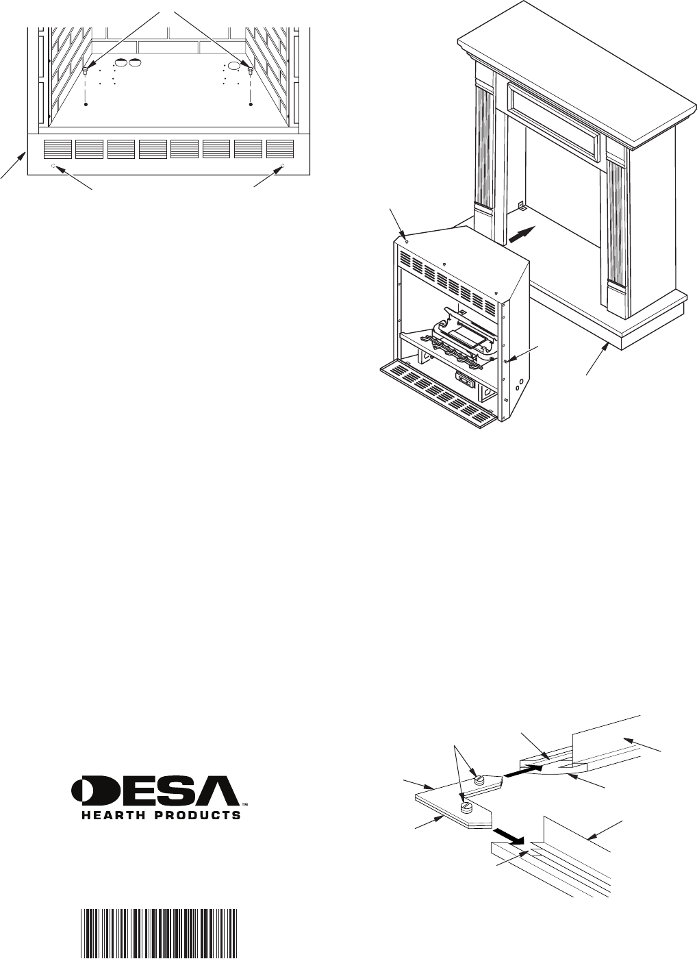
Figure 9 - Screw Locations for Gas Fireplace with Fixed
Louver
Screws
Holes are Behind Louver on
Fireplace Bottom for Attaching
Fireplace to Wooden Mantel Base
Fixed
Louver
121558-01
Rev. A
04/07
2701 Industrial Drive
P.O. Box 90004
Bowling Green, KY 42102-9004
1-866-672-6040
NOT A UPC
121558 01
INSTALLING FIREPLACE WITHOUT FLANGE
1. Place mantel assembly on wood base and center left to
right having back of assembly ush with back of base.
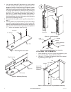
2. Attach mantel to base using 6 brackets and 1/2" screws,
3 per leg assembly into threaded holes in base and leg
assembly (see Figure 7, page 3).
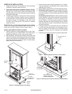
3. Position replace inside mantel (see Figure 10). Care-
fully position gas lines. IMPORTANT: Use caution when
positioning replace on base. Base may scratch easily.
4. : Lower bottom louver
door. Use two screws provided in replace hardware
package and attach replace to wooden base (see Figure
8, page 3). Close louver door
: Before installing logs or
burner assembly (see owner’s manual) remove screws
securing oor to assembly. Lift oor for access to bot-
tom of replace. Use two screws provided in replace
hardware package and attach replace base to wooden
base (see Figure 9). Reinstall oor with screws removed
previously.
5. If using perimeter trim that came with your mantel and it
has not yet been assembled, see Assembling Perimeter
Trim. Place metal trim on shoulder screws on replace.
Firmly snap trim assembly over shoulder screws.
6. Carefully push mantel and base into position against
wall.
Figure 10 - Installing Fireplace without Flange
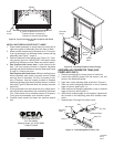
1. Remove packaging from three pieces of metal trim.
2. Locate two adjusting plates with set screws, and two
shims in the hardware packet.
3. Align shim under adjusting plate as shown in Figure 11.
4. Slide one end of adjusting plate/shim in slot on mitered
edge of top trim (see Figure 11).
5. Slide other end of adjusting plate/shim in slot on mitered
edge of side trim (see Figure 11).
6. While rmly holding edges of trim together, tighten both
set screws on the adjusting plate with slotted screw-
driver.
7. Repeat steps 2 through 6 for other corner.
Mantel
Base
Shoulder
Screw
Shoulder
Screw
Figure 11 - Assembling Metal Firebox Trim
Side Trim
Slot
Top Trim
Mitered Edge
Shim
Set Screws
Adjusting
Plate
Slot