


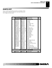
105270
For more information, visit www.desatech.com
For more information, visit www.desatech.com
22
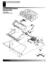
LOGS
• If you remove logs for cleaning, refer to Installing Logs, pages
15 and 16, to properly replace logs.
• Replace log(s) if broken or chipped (dime-sized or larger).
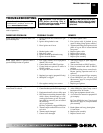
MAIN BURNER
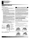
Periodically inspect all burner flame holes with the fireplace run-
ning. All slotted burner flame holes should be open with yellow
flame present. All round burner flame holes should be open with a
small blue flame present. Some burner flame holes may become
blocked by debris or rust, with no flame present. If so, turn off
fireplace and let cool. Remove blockage. Blocked burner flame
holes will create soot.
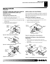
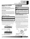
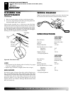
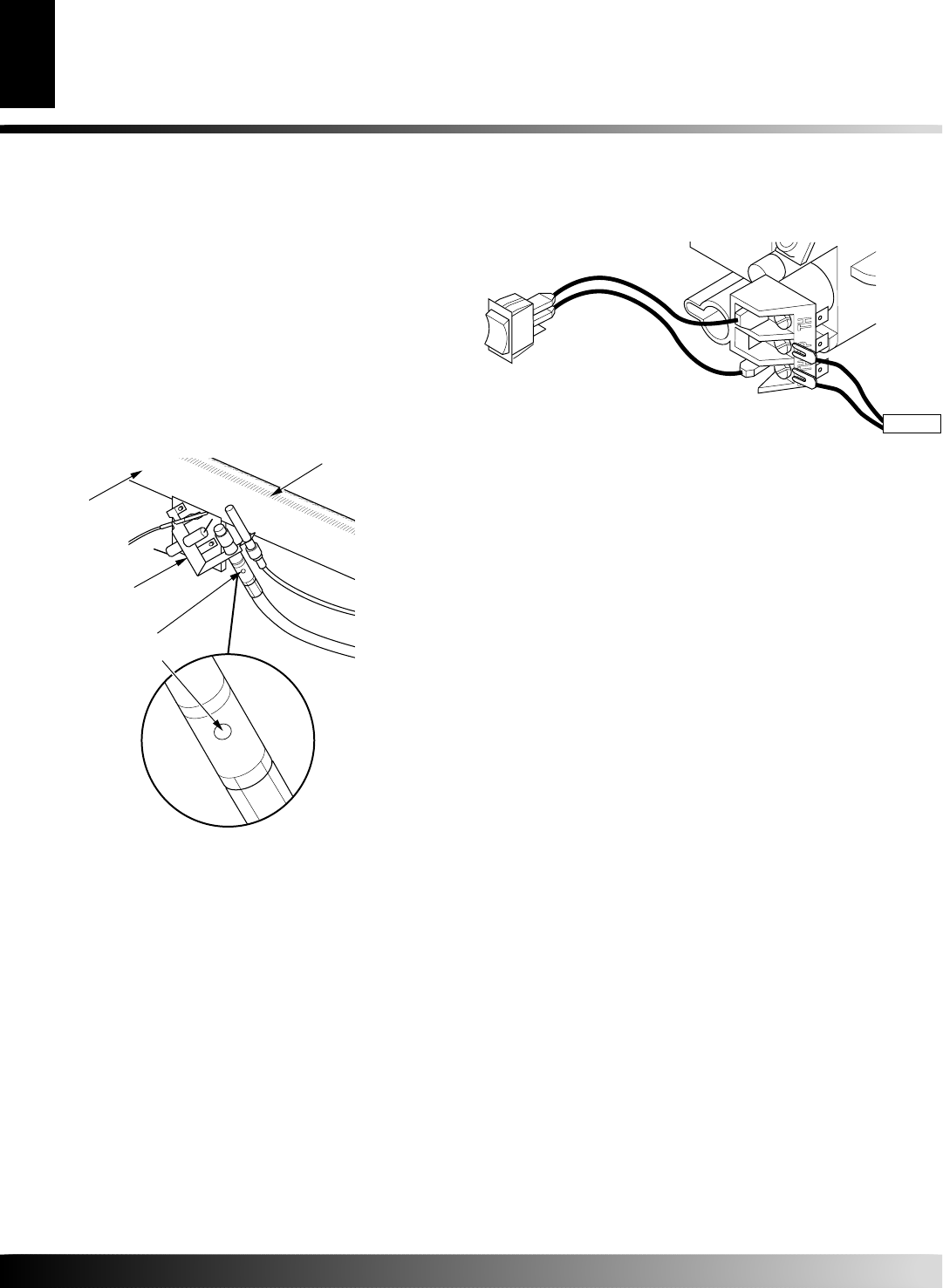
Figure 48 - Pilot Inlet Air Hole
Burner
Tube
Pilot
Assembly
Pilot Air
Inlet Hole
Ports/Slots
CLEANING AND MAINTENANCE
Cleaning Burner Injector Holder and Pilot Air Inlet Hole (Cont.)
Logs
Main Burner
WIRING DIAGRAM
SPECIFICATIONS
5. Blow air into the primary air holes on the injector holder.
6. In case any large clumps of dust have now been pushed into
the burner repeat steps 3 and 4, page 21.
Clean the pilot assembly also. A yellow tip on the pilot flame
indicates dust and dirt in the pilot assembly. There is a small pilot
air inlet hole about two inches from where the pilot flame comes
out of the pilot assembly (see Figure 48). With the unit off, lightly
blow air through the air inlet hole. You may blow through a
drinking straw if compressed air is not available.
CLEANING AND
MAINTENANCE
Continued
SPECIFICATIONS
VYGF33NRA
FPVF33NR
Btu (Variable) 20,000/30,000
Type Gas Natural Gas Only
Ignition Piezo
Pressure Manifold 3.5" W.C.
Inlet Gas Pressure (in. of water)
Maximum 10.5"
Minimum* 5"
Shipping Weight 122 lbs.
* For input adjustment
VYGF33PRA
FPVF33PR
Btu (Variable) 20,000/33,000
Type Gas Propane/LP Only
Ignition Piezo
Pressure Manifold 8.0" W.C.
Inlet Gas Pressure (in. of water)
Maximum 14"
Minimum* 11"
Shipping Weight 122 lbs.
* For input adjustment
A
U
T
O
O
F
F
ON
Thermopile
WIRING DIAGRAM
Note
: For proper operation of optional accessories, the wires from
the switch to the control must be connected exactly as shown.