


111252-01A
For more information, visit www.desatech.com
For more information, visit www.desatech.com
21
21
FIREPLACE INSTALLATION
Continued
FIREPLACE INSTALLATION
Checking Gas Connections (Cont.)
Installing Optional Wireless Hand-Held Remote Control - (C)GHRCB and (C)GHRCTB Series
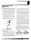
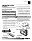
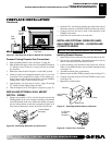
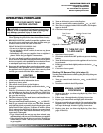
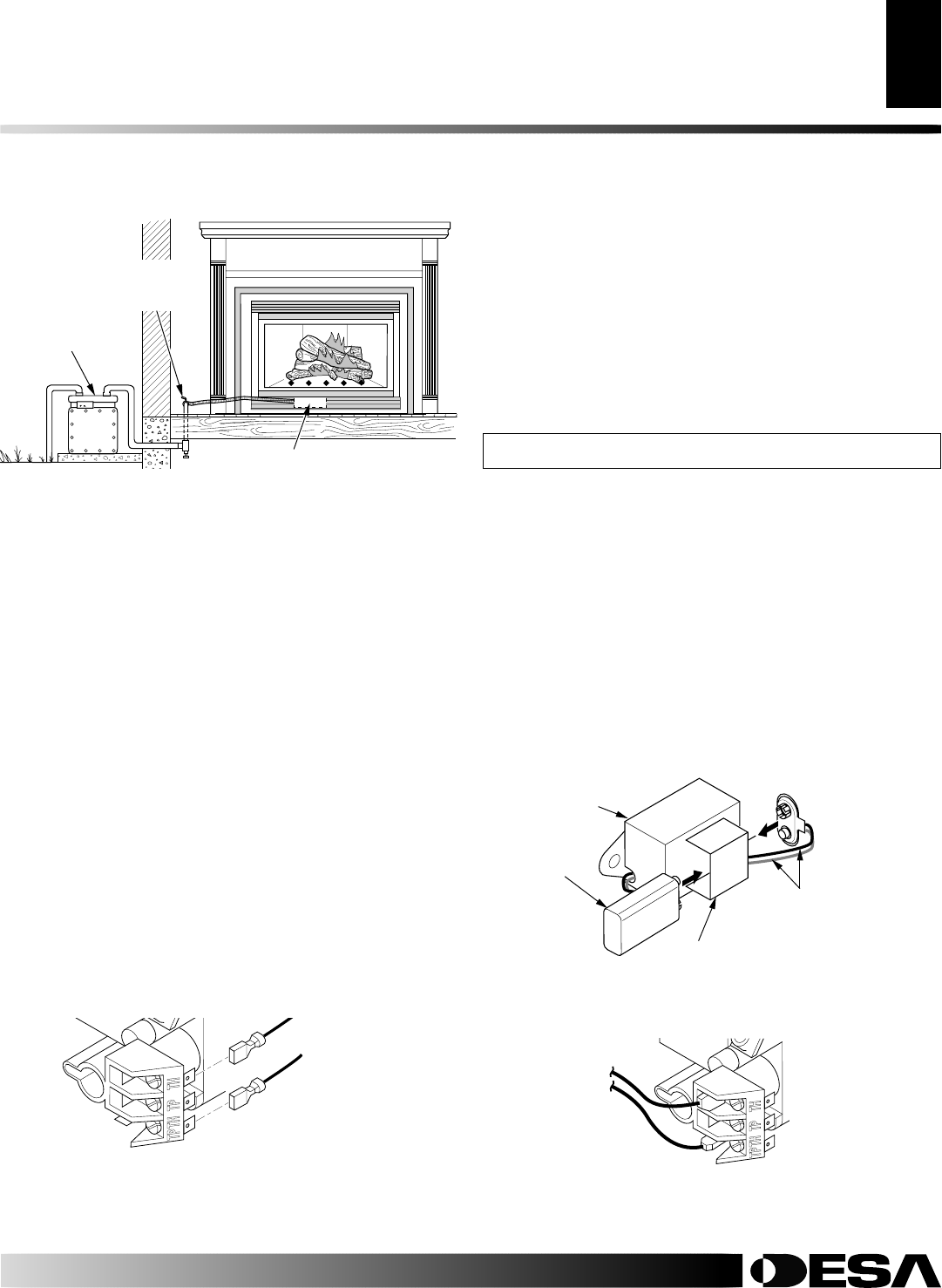
Figure 35 - Checking Gas Joints for Natural Gas Fireplace
Gas
Meter
Gas Valve
Equipment
Shutoff
Valve
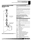
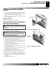
Installing Remote Receiver
1. Open bottom louver and locate the switch bracket on the left.
2. Unscrew the switch bracket. Lean bracket forward so you are
able to access the back of the remote receiver.
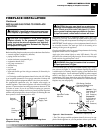
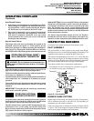
3. Locate the battery clip mounted on the back of the receiver.
Slide a 9-volt alkaline battery (not included) through the clip
(see Figure 37).
4. Attach the terminal wires to the battery.
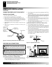
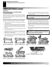
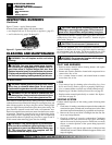
5. Remove wire from TH to TPTH on control valve (see Figure 37).
6. Connect wires from receiver to TH and TPTH to control valve
(see Figure 38).
7. Replace the switch bracket.
INSTALLING OPTIONAL WIRELESS HAND-
HELD REMOTE CONTROL - (C)GHRCB AND
(C)GHRCTB SERIES
NOTICE: Use only alkaline batteries (not included).
Figure 37 - Attaching Alkaline Battery to Receiver
Figure 38 - Control Valve Terminals
To Optional
Remote
Accessory
9-Volt Alkaline
Battery
Receiver
Terminal Wires
Battery Clip
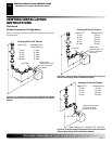
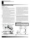
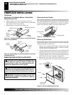
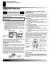
Figure 36 - Connecting Wall Swith to Control Valve
INSTALLING OPTIONAL WALL MOUNT
SWITCH - GWMS2
1. Connect one terminal of 25 ft. wire for the wall switch to the
TPTH terminal on the valve. Connect remaining wire terminal
to the TH terminal on the valve. Make sure that the wire termi-
nals are in the positions on the unit as pictured in Figure 36. If
wires are not connected as shown the switch will not work.
To Wall Switch
Accessory
Pressure Testing Fireplace Gas Connections
1. Open equipment shutoff valve (see Figure 33, page 20).
2. Open propane/LP supply tank valve for propane/LP fireplace
or main gas valve located on or near gas meter for natural
gas fireplace.
3. Make sure control knob of fireplace is in the OFF position.
4. Check all joints from equipment shutoff valve to gas valve
(see Figure 34 for propane/LP or Figure 35 for natural gas).
Apply noncorrosive leak detection fluid to all joints. Bubbles
forming show a leak. Correct all leaks at once.
5. Light fireplace (see Operating Fireplace, pages 25 through
27). Check all other internal joints for leaks.
6. Turn off fireplace (see To Turn Off Gas to Appliance, page 25).
2. Route the 25 ft. wire through openings provided on the sides of
the burner system to a convenient location to mount your switch.
3. Connect one bare wire end to each of the terminals of the
GWMS2 wall switch.
4. Install the wall switch and cover in the wall.