


111253-01A
For more information, visit www.desatech.com
For more information, visit www.desatech.com
16
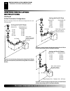
01798 Vertical Round High Wind Termination (1)
01800 Horizontal Square High Wind Termination (1)
01801 14" Snorkel Termination - Galvanized (1)
01802 36" Snorkel Termination - Galvanized (1)
DESA Venting Accessories
Number Description
01504 Firestop Plate (4)
01505 Adjustable Roof Flashing 0 to 8/12 - Galvanized (6)
01506 Steep Pitch Flashing 9/12 to 12/12 - Galvanized (6)
01507 Storm Collar - Galvanized (4)
01508 Wall Strap (4)
01514 Combustible Siding Standoff - Galvanized (1)
01607 Wall Firestop - Galvanized (4)
VR-58 Vertical Restrictor - Galvanized
VENTING INSTALLATION
INSTRUCTIONS
Continued
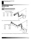
PARTS LISTS FOR VENTING KITS AND
COMPONENTS FOR VV361 SERIES
DESA (5/8") Pipe & Vent Kits
Number Description
01492 Horizontal Square Termination Kit
Includes: 45° Elbow (Through 5" Wall), Wall Firestop,
Horizontal Square Termination
01493 Basic Vertical Termination Kit
Includes: Vertical Termination, Adjustable Flashing,
Storm Collar
01491 Horizontal Round Termination Kit
Includes: Round Termination, Wall Firestop, and
45° Elbow (Through 5" Wall)
01497 12" Section Coaxial Pipe - Galvanized (4)
01498 18" Section Coaxial Pipe - Galvanized (4)
01499 24" Section Coaxial Pipe - Galvanized (4)
01500 36" Section Coaxial Pipe - Galvanized (4)
01501 48" Section Coaxial Pipe - Galvanized (4)
01513 6" Section Coaxial Pipe - Galvanized (4)
01606 Adjustable 17"-24" Section Coaxial Pipe -
Galvanized (4)
F8030 Adjustable 7"-12" Section Coaxial Pipe - Galvanized (6)
D1032 Adjustable 7"-12" Section Coaxial Pipe - Galvanized (1)
DESA Elbows
Number Description
01502 45° Elbow - Galvanized (4)
01503 90° Elbow - Galvanized (4)
DESA Terminations
Number Description
01494 Vertical Round Termination - Galvanized (1)
01495 Horizontal Round Termination - Galvanized (1)
01496 Horizontal Square Termination - Galvanized (1)
FIREPLACE INSTALLATION
VENTING INSTALLATION INSTRUCTIONS
Parts Lists for Venting Kits and Components
FIREPLACE INSTALLATION
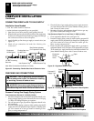
Check Gas Type
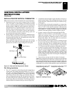
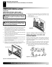
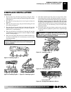
Installing Optional Blower Accessory
Model BK Installation
Follow all instructions provided in the blower accessory kit.
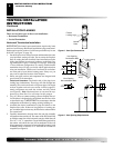
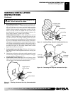
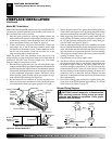
1. Attach the power cord to the blower motor by firmly pushing the
two female terminals at the end of the power cord onto the two
spade terminals on the blower motor (see Figure 25, page 17).
2. Attach green ground wire from power cord to blower hous-
ing using screw provided (see Figure 25, page 17). Tighten
screws securely.
3. Place the blower against the lower rear wall of the firebox outer
wrapper with the exhaust port directed upward. The blower
will fit inside the back opening and be held in position against
the back wall by the magnets (see Figure 25, page 17).
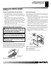
INSTALLING OPTIONAL BLOWER
ACCESSORY
NOTICE: If installing blower in an existing fireplace
with gas connections, shut off gas supply and dis-
connect heater from gas supply. Contact a qualified
service person to do this.
WARNING: If there is a duplex electrical outlet
installed in the right side of the bottom of the fireplace
base area, be sure that the electrical power to the outlet
is turned off before proceeding with blower installation.
Failure to do this may result in serious injury.
CHECK GAS TYPE
Use proper gas type for the fireplace unit you are installing. If your
gas supply is not correct, do not install fireplace. See retailer where
you purchased the fireplace for proper fireplace according to your
gas type.
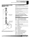
PARTS LISTS FOR VENTING KITS AND
COMPONENTS FOR V36 AND VV36 SERIES (CONT.)
Number Description
RF-58-12 Roof Flashing - 6/12 to 12/12 Pitch, Galvanized
VR-58 Vertical Restrictor, Galvanized
S-58 Vinyl Siding Standoff, Galvanized
WS-58 Wall Strap
CS-58 Cathedral Ceiling Support
FP-58 Firestop Plate
SF-58 Stucco Flashing - For use with HTS-5