


111251-01D
For more information, visit www.desatech.com
For more information, visit www.desatech.com
16
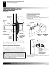
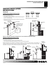
VENTING INSTALLATION
INSTRUCTIONS
Continued
PARTS LISTS FOR VENTING KITS AND
COMPONENTS
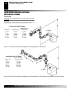
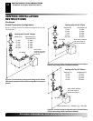
DESA Pipe & Vent Kits
Number Description
P47-6 6" Section Coaxial Pipe - Galvanized
P47-12 12" Section Coaxial Pipe - Galvanized
P47-24 24" Section Coaxial Pipe - Galvanized
P47-36 36" Section Coaxial Pipe - Galvanized
P47-48 48" Section Coaxial Pipe - Galvanized
PA47-712 Adjustable 7"-12" Section Coaxial Pipe - Galvanized
VKG-47 Ground Floor Vent Kit - Galvanized
Includes: 45° Elbow, 7"-12" Adjustable Pipe, Wall Firestop,
Horizontal Square Termination, and 16 Screws
VKB-47 Basement Vent Kit - Galvanized
Includes: 45° Elbow, 7"-12" Adjustable Pipe, Wall
Firestop, Horizontal Square Termination, 4' Pipe, 90°
Elbow, and 20 Screws
VKS-47 Snorkel Kit - Galvanized
Includes: 45° Elbow, 7"-12" Adjustable Pipe, Wall
Firestop, 36" Snorkel Termination, 4' Pipe, 90° Elbow,
and 26 Screws
VKR-47 Roof Vent Kit - Galvanized
Includes: 45° Elbow, 7"-12" Adjustable Pipe, Flue Re-
strictor, Vertical High Wind Termination, 2' Pipe, 4' Pipe,
Firestop Plate, Roof Flashing (0/12-6/12), and 26 Screws
VKC-47 Corner Vent Kit - Galvanized
Includes: 45° Elbow, 7"-12" Adjustable Pipe, Hori-
zontal Termination, 6" Pipe, 90° Elbow, Wall Firestop,
and 18 Screws
HTK Horizontal Round Termination Kit
Includes: Round Termination, Wall Firestop, and 45° Elbow
HTKS-47 Horizontal Square Termination Kit
Includes: Square Termination, Wall Firestop, and 45° Elbow
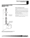
DESA Elbows
Number Description
E47-45 45° Elbow - Galvanized
E47-90 90° Elbow - Galvanized
DESA Terminations
Number Description
HT-47 Horizontal Round Termination - Galvanized
HTS-47 Horizontal Square Termination - Galvanized
VT-47 Vertical Round Termination - Galvanized
ST-47-14 14" Snorkel Termination - Galvanized
ST-47-36 36" Snorkel Termination - Galvanized
DESA Venting Accessories
Number Description
SC-47 Storm Collar - Galvanized
WF-47 Wall Firestop - Galvanized
RF-47-6 Roof Flashing - 0 to 6/12 Pitch - Galvanized
RF-47-12 Roof Flashing - 6/12 to 12/12 Pitch - Galvanized
VR-47 Vertical Restrictor - Galvanized
S-47 Combustible Siding Standoff - Galvanized
WS-47 Wall Strap
FP-47 Firestop Plate
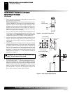
FIREPLACE INSTALLATION
VENTING INSTALLATION INSTRUCTIONS
Parts Lists for Venting Kits and Components
FIREPLACE INSTALLATION
Check Gas Type
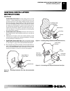
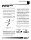
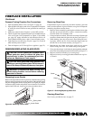
Installing Optional Blower Accessories
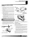
Model BK Installation
Follow all instructions provided in the blower accessory kit.
1. Attach the power cord to the blower motor by firmly pushing the
two female terminals at the end of the power cord onto the two
spade terminals on the blower motor (see Figure 25, page 17).
2. Attach green ground wire from power cord to blower hous-
ing using screw provided (see Figure 25, page 17). Tighten
screws securely.
3. Place the blower against the lower rear wall of the firebox outer
wrapper with the exhaust port directed upward. The blower
will fit inside the back opening and be held in position against
the back wall by the magnets (see Figure 25, page 17).
INSTALLING OPTIONAL BLOWER
ACCESSORIES
NOTICE: If installing blower in an existing fireplace
with gas connections, shut off gas supply and dis-
connect heater from gas supply. Contact a qualified
service person to do this.
WARNING: If there is a duplex electrical outlet
installed in the right side of the bottom of the fireplace
base area, be sure that the electrical power to the outlet
is turned off before proceeding with blower installation.
Failure to do this may result in serious injury.
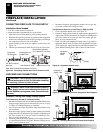
CHECK GAS TYPE
Use proper gas type for the fireplace unit you are installing. If your
gas supply is not correct, do not install fireplace. See retailer where
you purchased the fireplace for proper fireplace according to your
gas type or to purchase gas conversion kit (see Accessories, page 39).