


www.desatech.com
116292-01A
12
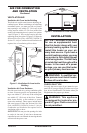
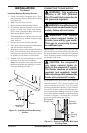
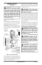
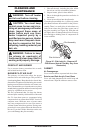
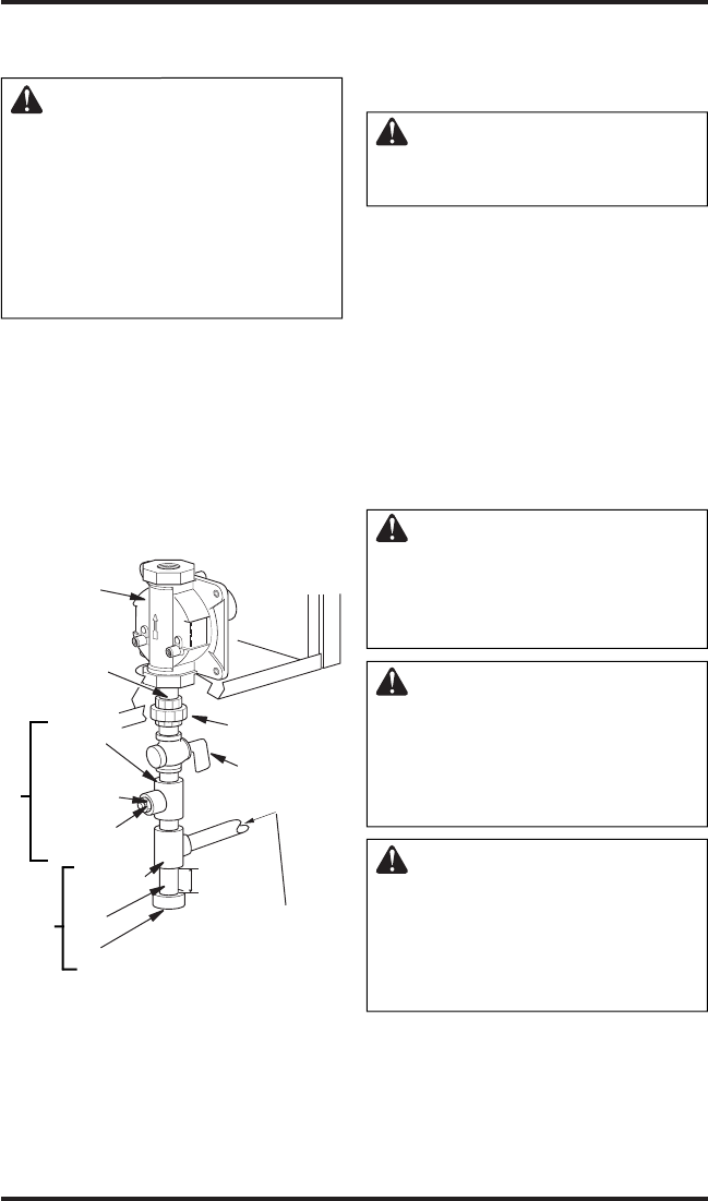
Tee Joint
Reducer
Bushing to
1/8" NPT
1/8" NPT
Plug Tap
Test Gauge Connection*
3/8" NPT
Pipe Nipple
Heater
Cabinet
Equipment
Shutoff
Valve *
3"
(7.6 cm)
Min.
Natural Gas
From Gas Meter (4" W.C.
to 10.5" W.C. Pressure)
Propane/LP
From External Regulator
(11" W.C. to 14" W.C.
Pressure)
Ground Joint
Union
Tee Joint
Pipe
Nipple
Cap
Sediment Trap
Figure 14 - Gas Connection
INSTALLATION
Continued
Pressure
Regulator
* A CSA design-certified equipment shutoff valve
with 1/8" NPT tap is an acceptable alternative to
test gauge connection. Purchase the optional CSA
design-certified equipment shutoff valve from your
dealer. See
Accessories, page 23.
CAUTION: Use only new,
black iron or steel pipe. Inter-
nally-tinned copper tubing may
be used in certain areas. Check
your local codes. Use pipe of
large enough diameter to allow
proper gas volume to heater. If
pipe is too small, undue loss of
volume will occur.
Typical Inlet Pipe Diameter - 3/8" (9.5 mm)
or greater
Installation must include equipment shutoff valve,
union and plugged 1/8" NPT tap. Locate NPT tap
within reach for test gauge hook up. NPT tap must
be upstream from heater (see Figure 14).
IMPORTANT: Install an equipment shutoff valve
in an accessible location. The equipment shutoff
valve is for turning on or shutting off the gas to
the appliance.
Apply pipe joint sealant lightly to male NPT
threads. This will prevent excess sealant from
going into pipe. Excess sealant in pipe could result
in clogged heater valves.
WARNING: Use pipe joint
sealant that is resistant to liquid
petroleum (LP) gas.
Install sediment trap in supply line as shown in
Figure 14. Locate sediment trap where it is within
reach for cleaning. Locate sediment trap where
trapped matter is not likely to freeze. A sediment
trap traps moisture and contaminants. This keeps
them from going into heater controls. If sediment
trap is not installed or is installed wrong, heater
may not run properly.
IMPORTANT: Hold the pressure regulator with
wrench when connecting it to gas piping and/or
fittings. Do not over tighten pipe connection to
regulator. The regulator body could be damaged.
CHECKING GAS CONNECTIONS
WARNING: Test all gas piping
and connections, internal and
external to unit, for leaks after
installing or servicing. Correct
all leaks at once.
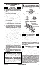
WARNING: Never use an
open flame to check for a leak.
Apply a noncorrosive leak detec-
tion fluid to all joints. Bubbles
forming show a leak. Correct all
leaks at once.
CAUTION: For propane/LP
gas, make sure external regula-
tor has been installed between
propane/LP supply and heater.
See guidelines under Connect-
ing to Gas Supply, page 11.