


11
104416
OWNER’S MANUAL
Installation Items Needed
Before installing heater, make sure you have
the items listed below.
• piping (check local codes)
• sealant (resistant to propane/LP gas)
• manual shutoff valve *
• test gauge connection *
• sediment trap
• tee joint
• pipe wrench
CONNECTING TO GAS
SUPPLY
NOTICE: A qualified service per-
son must connect heater to gas
supply. Follow all local codes.
INSTALLATION
Continued
* An A.G.A. design-certified manual shutoff
valve with 1/8" NPT tap is an acceptable
alternative to test gauge connection. Pur-
chase the optional A.G.A. design-certified
manual shutoff valve from your dealer. See
Accessories, page 25.
WARNING: Never connect
heater to private (non-utility) gas
wells. This gas is commonly
known as wellhead gas.
CAUTION: Use only new, black
iron or steel pipe. Internally-tinned
copper tubing may be used in
certain areas. Check your local
codes. Use pipe of 1/2" diameter
or greater to allow proper gas vol-
ume to heater. If pipe is too small,
undue loss of pressure will occur.
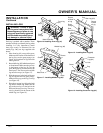
Installation must include a manual shutoff
valve, union, and plugged 1/8" NPT tap.
Locate NPT tap within reach for test
gauge hook up. NPT tap must be upstream
from heater (see Figure 13).
Apply pipe joint sealant lightly to male
threads. This will prevent excess sealant
from going into pipe. Excess sealant in
pipe could result in clogged heater valves.
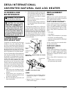
We recommend that you install a sediment
trap in supply line as shown in Figure 13.
Locate sediment trap where it is within
reach for cleaning. Install in piping system
between fuel supply and heater. Locate
sediment trap where trapped matter is not
likely to freeze. A sediment trap traps
moisture and contaminants. This keeps
them from going into heater controls. If
sediment trap is not installed or is installed
wrong, heater may not run properly.
CAUTION: Avoid damage to
gas control. Hold gas control with
wrench when connecting it to gas
piping and/or fittings.
* Purchase the optional A.G.A. design-certified manual shutoff valve from your dealer.
See Accessories, page 25.
** Minimum inlet pressure for purpose of input adjustment.
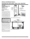
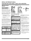
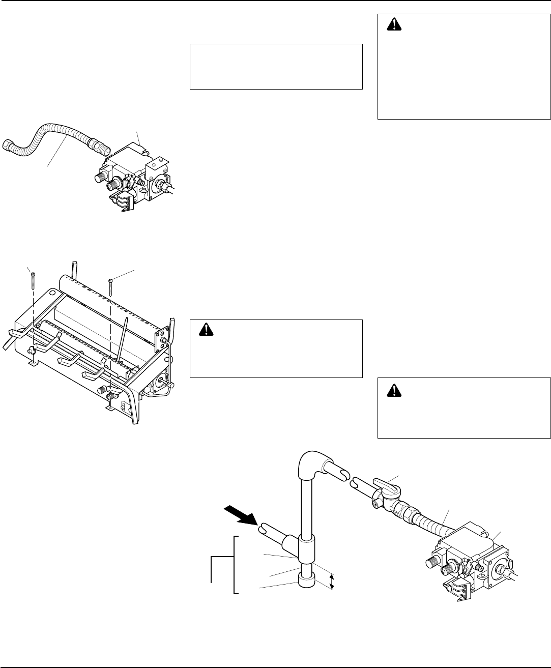
Figure 13 - Gas Connection
Continued
Tee
Joint
Pipe
Nipple
Cap
3" Minimum
Sediment
Trap
Gas Control
From Gas Meter
(5" W.C.** to 10.5"
W.C. Pressure)
A.G.A. Design-Certified Manual
Shutoff Valve With 1/8" NPT Tap*
Approved Flexible Gas Hose
(if allowed by local codes)
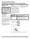
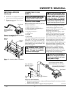
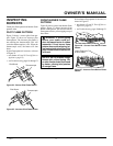
Figure 11 - Attaching Flexible Gas Hose
to Heater Gas Regulator
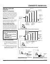
Figure 12 - Attaching Base to Fireplace
Floor
Gas Control
Flexible Gas Hose
(if allowed by local
codes)
Masonry
Screw
Masonry
Screw
6. Attach base to fireplace floor using
masonry screws (in hardware package).
7. Connect to gas supply. See Connect-
ing To Gas Supply.