


www.desatech.com
113061-01F 11
4. If installing bottom mounting screws into
hollow or solid wall, install wall anchors.
Follow steps 1 through 4 under Attaching To
Wall Anchor Method, page 10.
If installing bottom mounting screw into wall
stud, drill holes at marked locations using
9/64" drill bit.
5. Replace heater onto mounting bracket.
6. Place spacers between bottom mounting holes
and wall anchor or drilled hole.
7. Hold spacer in place with one hand. With other
hand, insert mounting screw through bottom
mounting hole and spacer. Place tip of screw
in opening of wall anchor or drilled hole.
8. Tighten both screws until heater is rmly
secured to wall. Do not over tighten.
Note: Do not replace front panel at this time.
Replace front panel after making gas connec-
tions and checking for leaks (see pages 11
through 13).
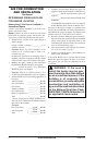
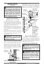
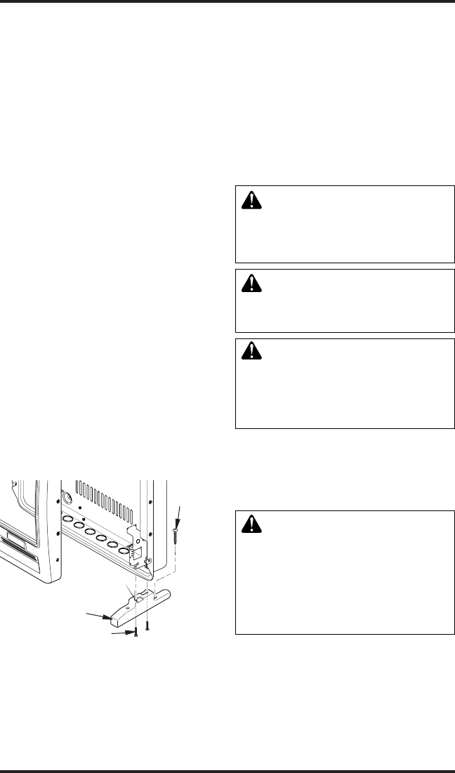
MOUNTING HEATER TO FLOOR
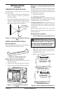
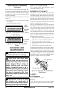
Mounting Base Feet to Heater
1. Lay heater cabinet on its back on a table with
the heater bottom overhanging the table edge.
2. Align holes in base foot with mounting holes
on bottom of cabinet (see Figure 13).
3. Secure base foot to heater using sheet metal
screws.
4. Repeat for other side.
INSTALLATION
Continued
Figure 13 - Installing Base Feet
Sheet Metal Screw
Base Foot
Wood
Screw
Mounting Base Feet to Floor (Where
required by local code)
1. Remove front cover (see Removing Front
Panel of Heater, page 9).
2. Position heater with base feet in desired loca-
tion. Mark holes for drilling. Remove heater
with base.
3. For carpeted oors, make a small cut with a
sharp knife at marked locations prior to drill-
ing. If mounting base to a wood oor, drill 1/8"
diameter hole, 3/4" deep. (Do not use anchors
in wood oors).
If mounting base to a concrete oor, drill with
1/4" diameter concrete drill bit, 1
3
/8" into oor.
Insert anchors completely into holes.
4. Reposition heater with base feet over holes.
Secure base to oor with wood screws. See
Figure 13.
CONNECTING TO GAS SUPPLY
WARNING: This appliance
requires a 3/8" NPT (National
Pipe Thread) inlet connection to
the pressure regulator.
WARNING: A qualied service
person must connect heater to gas
supply. Follow all local codes.
WARNING: For natural
gas, never connect heater to
private (non-utility) gas wells.
This gas is commonly known
as wellhead gas.
IMPORTANT: For natural gas, check gas line
pressure before connecting heater to gas line. Gas
line pressure must be no greater than 10.5" of wa-
ter. If gas line pressure is higher, heater regulator
damage could occur.
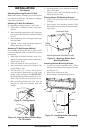
CAUTION: For propane/LP
gas, never connect heater di-
rectly to the propane/LP supply.
This heater requires an external
regulator (not supplied). Install
the external regulator between the
heater and propane/LP supply.
For propane/LP gas, the installer must supply an
external regulator. The external regulator will
reduce incoming gas pressure. You must reduce
incoming gas pressure to between 11" and 14" of
water. If you do not reduce incoming gas pressure,
heater regulator damage could occur. Install the
external regulator with the vent pointing down as
shown in Figure 14, page 12. Pointing the vent
down protects it from freezing rain or sleet.