


www.desatech.com
17113052-01D
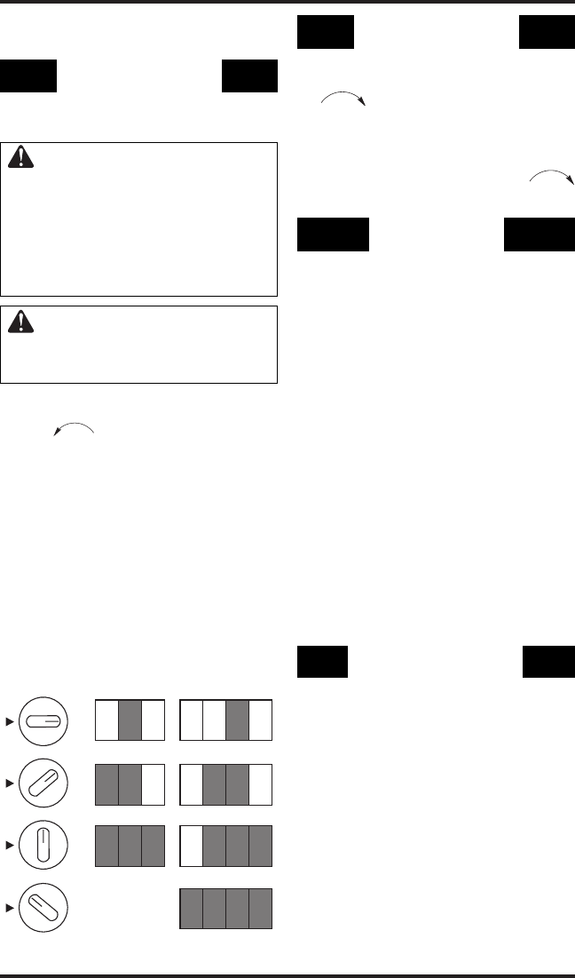
TO SELECT
HEATING LEVEL
INFRASTAT MODELS VP16ITA AND
VP22ITA ONLY
WARNING: When running
heater, set control knob at the
1, 2, 3 or 4 locked positions.
Never set control knob between
locked positions. Poor combus-
tion and higher levels of carbon
monoxide may result.
CAUTION: Do not try to ad-
just heating levels by using the
equipment shutoff valve.
1. Slightly press in plaque control knob on
right side of heater and turn counterclock
-
wise to the desired position.
IMPORTANT: Release downward pressure
while turning control knob. Control knob
will lock at the desired position.
2. For standard models (T), turn thermostat
control knob on left side of heater to any set
-
ting between LO and HI. For infrastat models
(ITA), set thermostat control knob at the 1, 2,
3 or 4, locked positions. Note: When burn
-
ers cycle on, (from LO to HI or one locked
positions to another) a “click” will be heard.
When the burners light, a “whoosh” noise
will be heard.
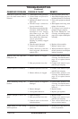
OPERATING HEATER
Continued
TO TURN OFF GAS
TO APPLIANCE
Shutting Off Heater
1. Turn thermostat control knob clockwise
to the OFF position.
2. Turn off all electric power to the appliance
if service is to be performed.
Shutting Off Burner Only (pilot stays lit)
Turn thermostat control knob clockwise
to the PILOT position.
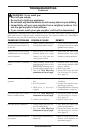
THERMOSTAT
OPERATION
The thermostatic control used on these models
differs from standard thermostats. Standard
thermostats simply turn on and off the burner.
The thermostat used on this heater senses the
room temperature. At times the room may ex
-
ceed the set temperature. If so, the burner will
shut off. The burner will cycle back on when
room temperature drops below the set tempera
-
ture. For standard models (T), the control knob
can be set to any heating level between 1 and 5.
All plaques will turn off and on. For infrastat
models (ITA), the control knob can be set at
the 1, 2, 3 or 4 locked positions for the desired
comfort level. The number of plaques selected
will turn off and on.
Note: The thermostat sensing bulb measures
the temperature of air near the heater cabinet.
This may not always agree with room tem
-
perature (depending on housing construction,
installation location, room size, open air tem-
peratures, etc.) Frequent use of your heater will
let you determine your own comfort levels.
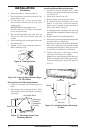
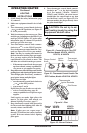
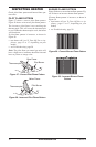
MANUAL LIGHTING
PROCEDURE
1. Remove front panel (see Figure 7, page 8).
2. Follow steps 1 through 5 under Lighting
Instructions, page 16.
3. With thermostat control knob pressed in,
strike match. Hold match to pilot until pilot
lights.
4. Keep thermostat control knob pressed in
for 30 seconds after lighting pilot. After 30
seconds, release control knob. Follow step
8 under
Lighting Instructions, page 16.
5. Replace front panel.
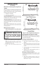
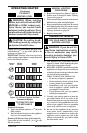
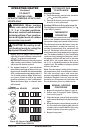
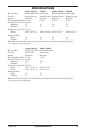
Plaque
Control Knob VP16ITA VP22ITA
Figure 26 - Burner Patterns, Models
VP16ITA and VP22ITA
1
2
3
4
1
2
3
4
1
2
3
4
1
2
3
4