


111115-01D
10
For more information, visit www.desatech.com
For more information, visit www.desatech.com
8. Remove heater base from fireplace. If installing optional con-
trol accessories, do so at this time. Follow all directions pro-
vided with accessory. See Installing Optional Remote Control
Accessories, below.
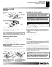
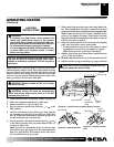
9. Drill holes at marked locations using 3/16" drill bit.
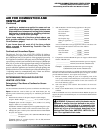
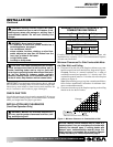
10. Attach base assembly to fireplace floor using two masonry
screws (in hardware package).
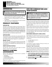
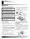
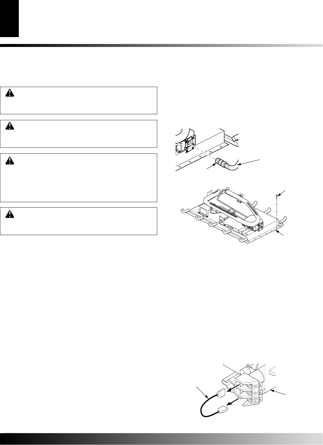
Fitting
Flexible Gas Hose
(if allowed by local
codes)
O
F
F
P
I
L
O
T
O
N
H
I
L
O
O
F
F
P
I
L
O
T
O
N
H
I
L
O
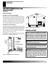
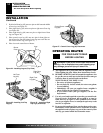
Figure 11 - Attaching Flexible Gas Hose to Heater
Figure 12 - Attaching Base Assembly to Fireplace Floor
Masonry Screw
Mounting
Flange
INSTALLATION
Continued
INSTALLING HEATER BASE ASSEMBLY
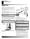
WARNING: If installing in a sunken fireplace, special
care is needed. You must raise the fireplace floor to
allow access to heater control panel. This will insure
adequate air flow and guard against sooting and con-
trols being damaged. Raise fireplace floor with noncom-
bustible material. Make sure material is secure.
CAUTION: Do not pick up heater base assembly
by the burner. This could damage heater. Only handle
base assembly by grates.
WARNING: You must secure this heater to fire-
place floor. If not, heater will move when you adjust
controls. Moving heater may cause a gas leak.
IMPORTANT:
Make sure the heater burner is level. If heater is not
level, heater will not work properly.
Installation Items Needed
• hardware package (provided with heater)
• approved flexible gas hose (not provided) (if allowed by local
codes)
• sealant (resistant to propane/LP gas, not provided)
• electric drill with 3/16" drill bit (metal or masonry as applicable)
• flathead screwdriver
1. Apply pipe joint sealant lightly to male threads of the fitting to
be threaded into gas control. Connect approved flexible gas hose
to gas control fitting in heater (see Figure 11).
IMPORTANT:
Hold gas fitting with wrench when connecting flexible gas hose.
2. Locate two masonry screws in hardware package.
3. Place heater base in fireplace.
4. Place logs in their proper position on heater base. See Install-
ing Logs, pages 13 and 14.
5. Center heater base and logs front-to-back and side-to-side in
fireplace.
6. Carefully remove logs without moving heater base.
7. Mark screw locations through one hole on each side of the
mounting bracket (see Figure 12). If installing in a brick-bot-
tom fireplace, mark screw locations in mortar joint of bricks.
CAUTION: Do not remove the data plates attached
to the heater base assembly. The data plates contain
important warranty and safety information.
INSTALLATION
Installing Heater Base Assembly
Installing Optional Remote Control Accessories
INSTALLING OPTIONAL REMOTE CONTROL
ACCESSORIES
Installing Remote Receiver
All remote control accessories are available separately (see Acces-
sories, page 27). The remote receiver for these accessories will be
installed using the bracket located on the front left side of the base.
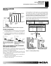
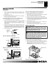
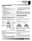
1. Disconnect jumper wire from control valve at TPTH and TH
locations (see Figure 13),
2, Install remote receiver into receiver bracket using push button
clips provided with receiver (see Figure 14, page 11).
3. Connect wires to control valve at the TPTH and TH locations
as shown in Figure 15, page 11.
Figure 13 - Disconnecting Jumper Wire from Control Valve
Jumper Wire
Control
Valve