


111640-01B
14
For more information, visit www.desatech.com
For more information, visit www.desatech.com
INSTALLATION
Installing Optional Remote Accessories (Cont.)
Installing Logs
INSTALLATION
Continued
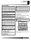
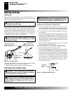
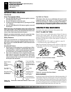
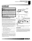
Installing 9-Volt Battery (Not Included) in Hand-
Held Remote Control Unit
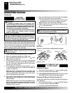
1. Remove battery cover on back of remote control unit.
2. Attach terminal wires to the battery. Place battery into the bat-
tery housing.
3. Replace battery cover onto remote control unit.
Battery Cover
9-Volt
Battery
Terminal
Wires
Figure 22 - Installing Battery in Hand-Held Remote Control Unit
(CGHRCB Series)
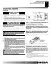
Remote
Control Unit
Battery
Housing
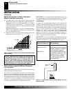
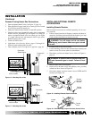
Figure 23 - Installing Battery in Hand-Held Remote Control Unit
(CGHRCTB Series)
INSTALLING LOGS
WARNING: Failure to position the parts in accor-
dance with these diagrams or failure to use only parts
specifically approved with this heater may result in
property damage or personal injury.
CAUTION: After installation and periodically there-
after, check to ensure that no flame comes in contact
with any log. With the heater set to HI, check to see if
flames contact any log. If so, reposition logs accord-
ing to the log installation instructions in this manual.
Flames contacting logs will create soot.
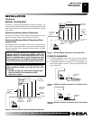
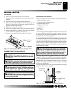
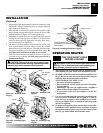
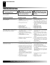
Figure 21 - Connecting Wires
Control
Valve
White
Wire From
Receiver
Red Wire From
Receiver
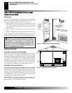
Installing Batteries for Remote Receiver and Hand
Held Remote Control
Two 9-volt alkaline batteries (not included) are required to operate
this heater with the wireless hand-held remote control set. One
battery must be installed in the receiver and one in the hand-held
remote control unit.
Note:
Only use alkaline batteries.
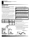
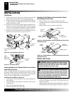
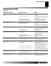
Installing 9-Volt Battery in Receiver
1. Locate back of receiver behind receiver bracket mounted on
base assembly.
2. Locate the battery clip mounted on the back of the receiver
(see Figure 20).
3. Slide a 9-volt battery through the clip.
4. Attach the terminal wires to the battery.
1. Align two pegs near rear of base behind support brackets with
two holes in bottom of rear log (#1). Place logs on pegs (see
Figure 24, page 15).
2. Align two pegs in left support bracket with holes in bottom of
left side log (#2). Place log on pegs (see Figure 25, page 15).
8. Install remote receiver into receiver bracket using pads and
push button clips provided with receiver (see Figure 20).
9. Connect wires to control valve at the TPTH and TH locations
as shown in Figure 21.
Note:
Make sure excess wire does not
interfere with burner or pilot.
10. If heater was removed from fireplace before installation of re-
mote accessory, see Installing Heater Base Assembly on pages
10 and 11 to reinstall heater into fireplace. Test gas connection
for leaks (see Checking Gas Connections, pages 11 and 12).
11. If logs were removed from heater for install remote accessory,
replace logs (see Installing Logs, pages 14 and 15).
Figure 20 - Installing Remote Receiver
Push Button
Clips
Bracket
Battery
Clip
9-Volt
Battery
Terminal
Wires
Pad
Battery
Housing
9-Volt
Battery
Battery Cover
Remote
Control Unit
Terminal
Wires