


www.desatech.com
109493-01N 9
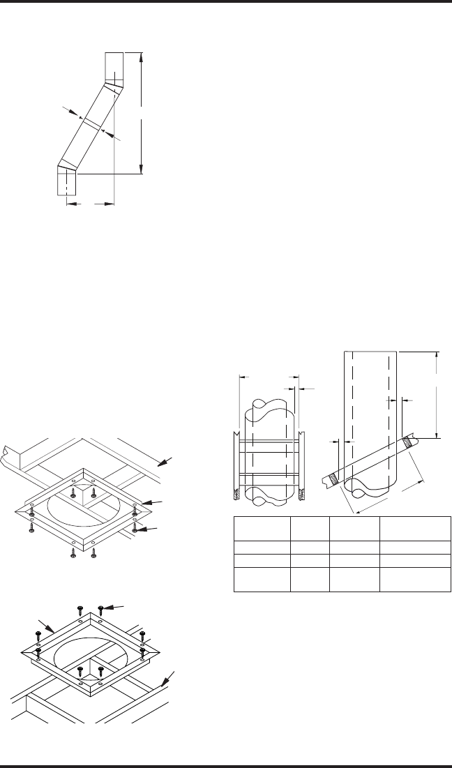
VENTING INSTALLATION
Continued
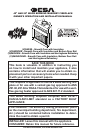
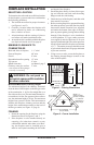
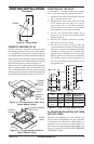
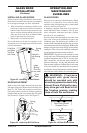
Figure 9 - Elbow Offset
B
A
Screws
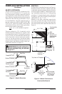
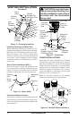
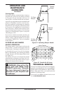
Firestop spacers are required at each point where
the chimney penetrates a oor space. Their purpose
is to establish and maintain the required clearance
between the chimney and the combustible materials.
When the pipe passes through a framed opening into
a living space above, the restop must be placed onto
the ceiling from below as shown in Figure 10.
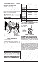
They also provide complete separation from one oor
space to another or attic space as required by most
codes. When the double wall pipe passes through a
framed opening into an attic space, the restop must
be placed into an attic oor as shown in Figure 11.
Figure 10 - Firestop Spacer with Living
Space Above Ceiling
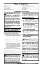
Figure 11 - Firestop Spacer with Attic
Space Above Ceiling
Existing
Ceiling
Frame
Firestop
Spacer
Screws or
Staples
(Min. of 8)
Firestop
Spacer
Screws or Staples
(Min. of 8)
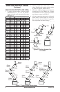
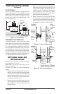
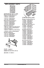
To maintain a 1" clearance to the pipe on a roof
with a pitch, a rectangular opening must be cut.
1. Determine the center point through which the
pipe will penetrate the roof.
2. Determine the center point of the roof. Pitch
is the distance the roof drops over a given
span, usually 12". A 6/12 pitch means that
the roof drops 6" for each 12" one measure
horizontally down from the roof rafters.
3. Use the roof opening chart (Figure 12) to
determine the correct opening length and
ashing required.
4. Remove the shingles around the opening
measured. Cut out this section.
5. Add the next sections of the pipe until the
end penetrates the roof line. Check to see that
the proper clearances are maintained. Extend
chimney by adding sections of double wall
pipe until pipe is minimum of 30" above the
highest point of the roof cutout. Termination
and chimney must extend a minimum of
36" above the highest point where it passes
through the roof.
19.5" Min.
30" Min.
2" Min.
2" Min.
2" Min.
Opening "A"
Pitch Slope Opening
Flat 0° 19.5" V6F-10DM
0-6/12 26.6° 22" V6F-10DM
6/12-
12/12
45.0° 27" V12F-10DM
Existing
Ceiling
Frame
Figure 12 - Roof Opening Measurements
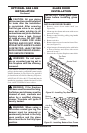
Determine the ashing to be used with the roof
opening chart. Slide ashing over pipe until base
is at against roof. Replace as many shingles as
needed to cover exposed area and ashing base.
Secure in position by nailing through shingles (see
Figure 13, page 10). DO NOT NAIL THROUGH
FLASHING CONE.