


16
105070
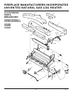
FIREPLACE MANUFACTURERS INCORPORATED
UNVENTED NATURAL GAS LOG HEATER
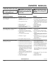
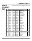
SPECIFICATIONS
18" Variable 24" Variable 30" Variable
Manually- Manually- Manually-
Controlled Controlled Controlled
Btu (Variable) 16,000/26,000 20,000/33,000 21,500/36,000
Type Gas Natural Gas Only Natural Gas Only Natural Gas Only
Ignition Piezo Piezo Piezo
Manifold Pressure 3.4" W.C. 3.4" W.C. 3.4" W.C.
Inlet Gas
Pressure (in. of water)
Maximum 10.5" 10.5" 10.5"
Minimum* 5" 5" 5"
Shipping Weight 26 lbs. 30 lbs. 34 lbs.
* For purpose of input adjustment
CLEANING AND
MAINTENANCE
WARNING: Turn off heater
and let cool before cleaning.
CAUTION: You must keep
control areas, burners, and cir-
culating air passageways of
heater clean. Inspect these areas
of heater before each use. Have
heater inspected yearly by a quali-
fied service person. Heater may
need more frequent cleaning due
to excessive lint from carpeting,
bedding material, pet hair, etc.
CLEANING BURNER
INJECTOR HOLDER AND
PILOT AIR INLET HOLE
The primary air inlet holes allow the proper
amount of air to mix with the gas. This
provides a clean burning flame. Keep these
holes clear of dust, dirt, lint, and pet hair.
Clean these air inlet holes prior to each
heating season. Blocked air holes will cre-
ate soot. We recommend that you clean the
unit every three months during operation
and have heater inspected yearly by a quali-
fied service person.
We also recommend that you keep the burner
tube and pilot assembly clean and free of
dust and dirt. To clean these parts we recom-
mend using compressed air no greater than
30 PSI. Your local computer store, hard-
ware store, or home center may carry com-
pressed air in a can. You can use a vacuum
cleaner in the blow position. If using com-
pressed air in a can, please follow the direc-
tions on the can. If you don't follow direc-
tions on the can, you could damage the pilot
assembly.
1. Shut off the unit, including the pilot.
Allow the unit to cool for at least thirty
minutes.
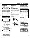
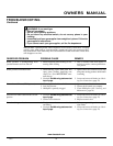
2. Inspect burner, pilot, and primary air
inlet holes on injector holder for dust
and dirt (see Figure 27).
3. Blow air through the ports/slots and
holes in the burner.
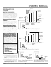
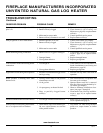
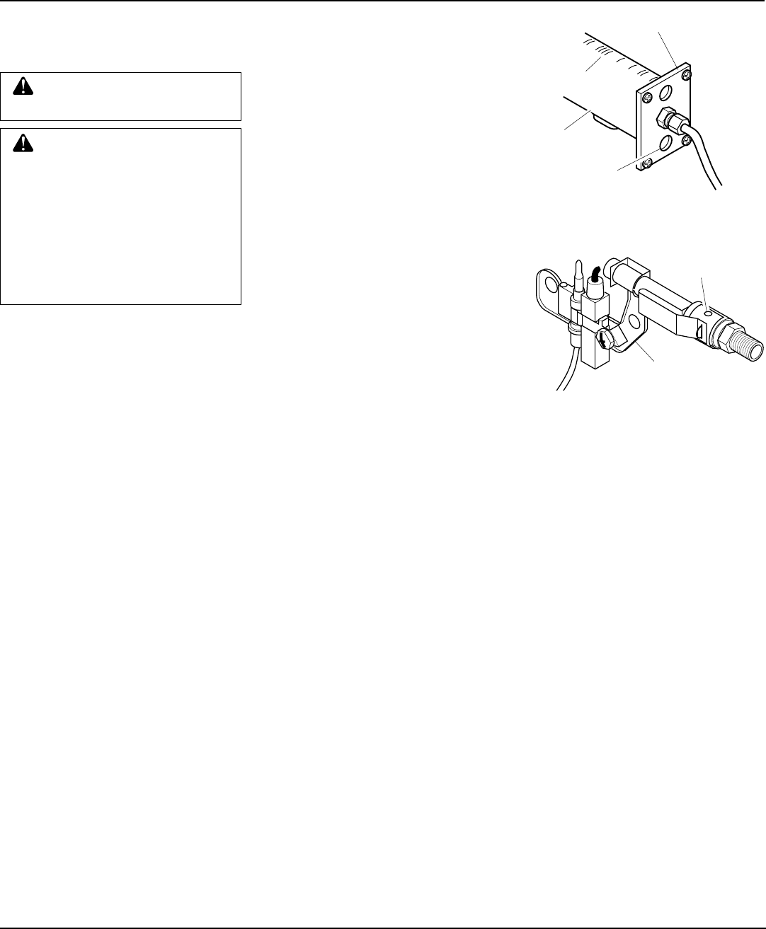
Figure 28 - Pilot Inlet Air Hole
Pilot Assembly
Pilot Air Inlet
Hole
4. Check the injector holder located at the
end of the burner tube again. Remove
any large particles of dust, dirt, lint, or
pet hair with a soft cloth or vacuum
cleaner nozzle.
5. Blow air into the primary air holes on
the injector holder.
6. In case any large clumps of dust have
now been pushed into the burner repeat
steps 3 and 4.
Clean the pilot assembly also. A yellow tip
on the pilot flame indicates dust and dirt in
the pilot assembly. There is a small pilot air
inlet hole about two inches from where the
pilot flame comes out of the pilot assembly
(see Figure 28). With the unit off, lightly
blow air through the air inlet hole. You may
blow through a drinking straw if compressed
air is not available.
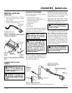
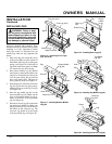
LOGS
• If you remove logs for cleaning, refer to
Installing Logs, page 13, to properly re-
place logs.
• Replace log(s) if broken or chipped
(dime-sized or larger).
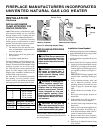
Figure 27 - Injector Holder On Outlet
Burner Tube
Burner
Tube
Injector Holder
Primary Air Inlet
Holes
Ports/Slots