


111826-01E
For more information, visit www.desatech.com
12
INSTALLATION
Continued
* Purchase the optional CSA design-cer ti fi ed equipment shutoff valve
from your dealer. See Accessories, page 27.
**Minimum inlet pressure for purpose of input adjustment.
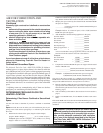
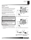
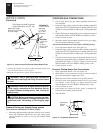
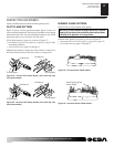
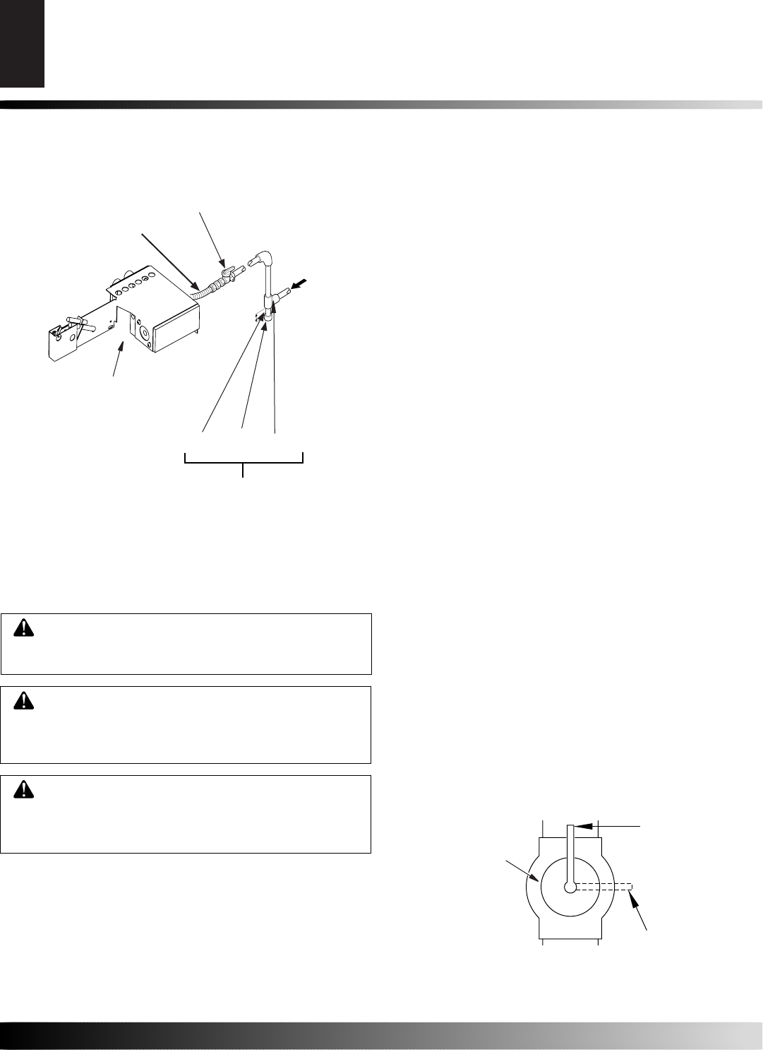
Figure 13 - Gas Connection (Remote-Ready Models Only)
Gas Control
Pipe Cap Tee
Nipple Joint
3" Minimum
Sediment Trap
PROPANE/LP
- From External
Regulator
(11" W.C.**
to 14" W.C.
Pressure)
NATURAL
- From Gas
Meter
(5" W.C.**
to 10.5" W.C.
Pressure)
CSA Design-Certifi ed Equipment
Shutoff Valve With 1/8" NPT Tap*
Approved Flexible
Gas Hose (if allowed
by local codes)
WARNING: Test all gas pip ing and connections
for leaks after in stall ing or serv ic ing. Cor rect all leaks
at once.
WARNING: Never use an open fl ame to check for
a leak. Apply a noncorrosive leak detection fl u id to
all joints. Bub bles form ing show a leak. Correct all
leaks at once.
CAUTION: Make sure ex ter nal regulator has been
installed between propane/LP supply and heat er. See
guidelines under Con nect ing to Gas Sup ply, page
11.
Pressure Testing gas Supply Piping system
Test Pressures In Excess Of 1/2 PSIG (3.5 kPa)
1. Disconnect appliance with its appliance main gas valve (control
valve) and equip ment shutoff valve from gas sup ply pip ing
sys tem. Pres sures in ex cess of 1/2 psig will dam age heat er
reg u la tor.
CHECKING GAS CONNECTIONS
INSTALLATION
Connecting To Gas Supply (Cont.)
Checking Gas Connections
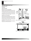
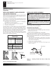
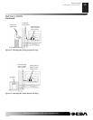
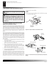
Figure 14 - Equipment Shutoff Valve
ON
POSITION
OFF
POSITION
Equipment
Shutoff
Valve
2. Cap off open end of gas pipe where equip ment shutoff valve
was con nect ed.
3. Pressurize supply pip ing sys tem by ei ther opening pro pane/LP
sup ply tank valve for propane/LP gas or opening main gas valve
lo cat ed on or near gas meter for natural gas, or using com pressed
air.
4. Check all joints of gas supply pip ing system. Apply non cor ro sive
leak detection fl u id to all joints. Bubbles form ing show a leak.
5. Correct all leaks at once.
6. Reconnect heater and equipment shutoff valve to gas supply.
Check re con nect ed fi ttings for leaks.
Test Pressures Equal To or Less Than 1/2 PSIG (3.5 kPa)
1. Close equipment shutoff valve (see Fig ure 14).
2. Pressurize supply pip ing sys tem by ei ther opening pro pane/LP
sup ply tank valve for propane/LP gas or opening main gas valve
lo cat ed on or near gas meter for natural gas, or using com pressed
air.
3. Check all joints from gas meter to equip ment shutoff valve for
natural gas or pro pane/LP sup ply to equip ment shutoff valve for
propane/LP (see Figure 15, page 13). Ap ply non cor ro sive leak
detection fl u id to all joints. Bub bles form ing show a leak.
4. Correct all leaks at once.
Pressure Testing Heater Gas Connections
1. Open equipment shutoff valve (see Fig ure 14).
2. Open main gas valve located on or near gas meter for natural
gas or open pro pane/LP supply tank valve.
3. Make sure control knob of heater is in the OFF position.
4. Check all joints from equipment shutoff valve to gas control
(see Fig ures 15 and 16 page 13). Ap ply non cor ro sive leak
de tec tion fl u id to all joints. Bub bles form ing show a leak.
5. Correct all leaks at once.
6. Light heater (see Operating Heater, pages 14 through 16).
Check all other internal joints for leaks.
7. Turn off heater.
(OPEN)
(CLOSE)