


111826-01E
For more information, visit www.desatech.com
11
11
INSTALLATION
Continued
INSTALLATION
Installing Heater Assembly (Cont.)
Connecting to Gas Supply
WARNING: This appliance requires a 3/8" NPT
(National Pipe Thread) inlet connection to the pres-
sure regulator.
WARNING: A qualifi ed ser vice per son must con-
nect heater to gas sup ply. Follow all local codes.
CAUTION: Never connect propane/LP fi replace
directly to the propane/LP supply. This heater re quires
an external regulator (not supplied). Install the ex-
ternal regu la tor be tween the heater and propane/LP
supply.
WARNING: Never connect natural gas fi replace to
pri vate (non-utility) gas wells. This gas is com mon ly
known as wellhead gas.
Installation Items Needed
Before installing heater, make sure you have the items listed be-
low.
• external regulator (supplied by installer)
• piping (check local codes)
• sealant (resistant to propane/LP gas)
• equipment shutoff valve *
• test gauge connection *
• sediment trap
• tee joint
• pipe wrench
• approved fl exible gas line with gas con nec tor (if allowed by lo cal
codes) (provided)
* A CSA design-certifi ed equipment shutoff valve with 1/8" NPT
tap is an ac cept able alternative to test gauge con nec tion. Pur chase
the optional CSA design-certifi ed equipment shutoff valve from
your dealer. See Accessories, page 27.
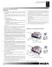
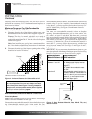
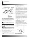
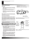
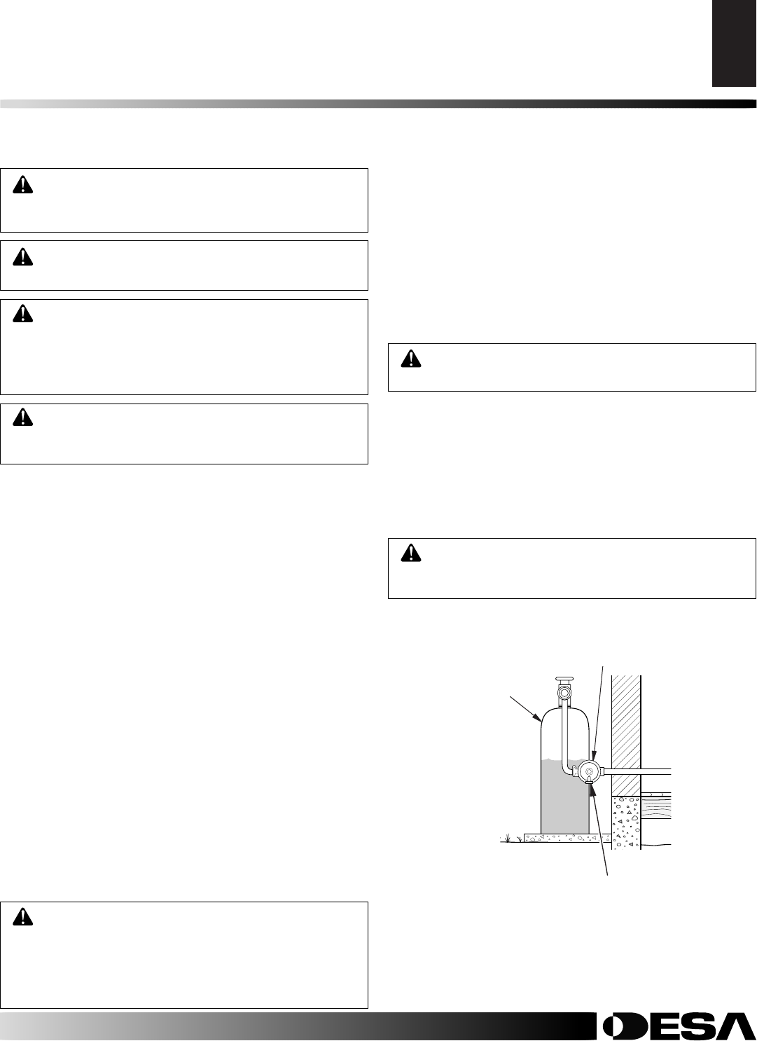
For propane/LP units, the installer must supply an external reg u -
la tor. The external reg u la tor will reduce incoming gas pressure. You
must reduce in com ing gas pressure to between 11 and 14 inches of
water. If you do not reduce in com ing gas pressure, heater regulator
damage could occur. Install external reg u la tor with the vent point-
ing down as shown in Figure 12. Pointing the vent down protects
it from freezing rain or sleet.
CAUTION: Use only new, black iron or steel pipe.
In ter nal ly-tinned copper tubing may be used in cer-
tain areas. Check your local codes. Use pipe of 1/2"
di am e ter or greater to allow prop er gas vol ume to
heater. If pipe is too small, undue loss of volume will
occur.
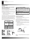
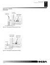
CONNECTING TO GAS SUPPLY
Installation must include an equipment shutoff valve, union, and
plugged 1/8" NPT tap. Locate NPT tap within reach for test gauge
hook up. NPT tap must be up stream from heater (see Figure 13
page 12, depending on your model).
IMPORTANT: Install equipment shutoff valve in an ac ces si ble
lo ca tion. The equip ment shutoff valve is for turning on or shut ting
off the gas to the appliance.
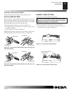
Apply pipe joint sealant lightly to male NPT threads. This will
prevent excess sealant from going into pipe. Excess sealant in pipe
could result in clogged heater valves.
WARNING: Use pipe joint seal ant that is resistant
to liquid pe tro leum (LP) gas.
We recommend that you install a sediment trap in sup ply line as
shown in Figure 13 page 12, depending on your model. Locate
sed i ment trap where it is with in reach for cleaning. Install in pip-
ing system between fuel supply and heater. Locate sed i ment trap
where trapped mat ter is not likely to freeze. A sediment trap traps
mois ture and con tam i nants. This keeps them from going into heater
controls. If sediment trap is not in stalled or is installed wrong, heater
may not run properly.
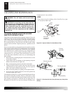
CAUTION: Avoid damage to gas control. Hold gas
control with wrench when connecting it to gas piping
and/or fi ttings.
Propane/LP
Supply Tank
External Regulator
Figure 12 - External Regulator With Vent Pointing Down
Vent Pointing Down