


111826-01E
For more information, visit www.desatech.com
10
INSTALLING DAMPER CLAMP ACCESSORY
FOR VENTED OPERATION
Note: When used as a vented decorative, ap pli ance must be installed
only in a solid-fuel burning fi replace with a working fl ue and con-
structed of noncombustible material.
If your heater is a non-thermostatically-controlled mod el, you may
use this heater as a vented prod uct. There are three reasons for op er -
at ing your heater in the vented mode.
1. The fi replace does not meet the clear ance to com bus ti bles
re quire ments for vent-free operation.
2. State or local codes do not permit vent-free operation.
3. You prefer vented operation.
If reasons number 1 or 2 above apply to you, you must permanently
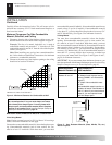
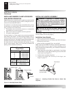
open chim ney fl ue damper. You must install the damper clamp ac-
cessory (to order, see Accessories, page 27). This will insure vented
op er a tion (see Figure 10). The damper clamp will keep damper open.
Installation instructions are included with clamp accessory.
See chart below for minimum permanent fl ue opening you must
provide. Attach damp er clamp so the minimum permanent fl ue
opening will be main tained at all times.
Area of Various Standard
Round Flues
Diameter (ins.) Area (sq. ins.)
5" 20 sq. inches
6" 29 sq. inches
7" 39 sq. inches
8" 51 sq. inches
Chimney Minimum Permanent
Height (ft.) Flue Opening (sq. ins.)
6' to 15' 39 sq. inches
15' to 30' 29 sq. inches
INSTALLATION
Continued
INSTALLING HEATER ASSEMBLY
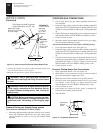
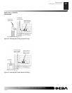
WARNING: If installing in a sunken fi re place,
special care is needed. You must raise the fi re place
fl oor to allow access to heat er control panel. This will
in sure ad e quate air fl ow and guard against soot ing.
Raise fi replace fl oor with noncom bus ti ble ma te ri al.
Make sure material is secure.
CAUTION: Do not pick up heat er as sem bly by
logs. This could damage unit. Only handle assembly
by grates.
IMPORTANT: Make sure the heater burn ers are level. If heater is
not level, heater will not work properly.
Installation Items Needed
• control cover kit (provided with heater)
• approved fl exible gas hose and fi ttings (pro vid ed with heater)
(if al lowed by lo cal codes)
• sealant (resistant to propane/LP gas, not pro vid ed)
Note: Install optional GHRCTA Receiver and Hand-Held Remote
Control Kit (see Ac ces so ries, page 27) before in stall ing gas log
heater (Remote-Ready Models Only). See installation in struc tions
in clud ed with the kit.
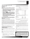
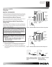
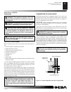
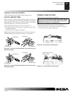
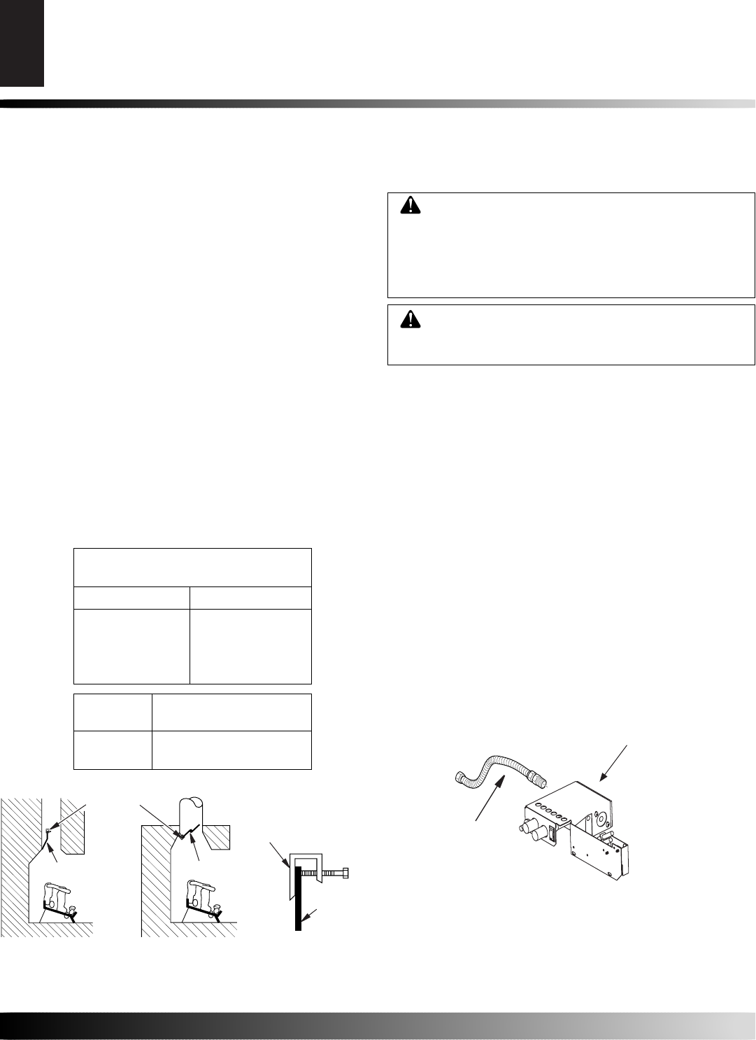
1. Apply pipe joint sealant lightly to male threads of gas fi tting
(not provided). Connect ap proved fl exible gas hose to inlet side
of gas con trol (see Figure 11).
2. Position heater assembly in fi re place.
3. Connect to gas supply. See Con nect ing To Gas Supply, (see
Figure 12, page 11).
INSTALLATION
Installing Damper Clamp Accessory for Vented Operation
Installing Heater Assembly
Figure 11 - Attaching Flexible Gas Hose to Heater Gas
Regulator
Gas Control
Flexible Gas
Hose (if allowed
by local codes)
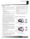
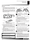
Figure 10 - Attaching Damper Clamp
Damper
Damper Clamp
Damper
Manufactured Fire place
Masonry Fire place
Damper Clamp
Damper