


www.desatech.com
120927-54B6
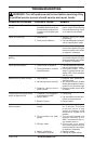
Note: It is strongly advised that you hire
a qualied professional to undertake this
step in order to prevent personal injury.
Once ue is capped, chimney is no longer
suitable for wood burning.
Note: Do not install this unit into a replace
that is prone to dampness; the area of instal-
lation must be dry.
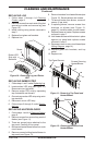
4. Plan the power supply. If an existing
grounded outlet is near replace, power
cord can run along front of replace. If
cord is not long enough to reach outlet, a
grounded extension cord minimum AWG
No. 14 and rated to a minimum of 1875
watts, may be used. If you plan to cut or drill
a hole in existing replace for wiring, it is
best to hire a professional to do this step in
order to prevent personal injury. To reduce
the risk of re, do not run power cord under
rugs, carpets, etc. Arrange power supply
cord away from high trafc areas where it
may pose a tripping hazard.
WARNING: The solid fuel/gas
replace has been converted for
use with an electric insert and
cannot be used for original fuels
unless all original parts have
been replaced and the replace
has been reapproved by the au-
thority having jurisdiction.
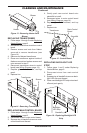
New Construction or Renovation
1. Select a location at least 3 feet (0.9 m)
away from combustible materials such
as curtains or drapes, furniture, bedding,
paper, etc.
2. Mark desired location on oor and store
unit in a safe, dry and dust free location.
3. Frame in an opening leaving at least 1/4"
(6 mm) around the edge of the unit (see
Framing). Any new wiring must be done in
compliance with local and national codes
and other applicable regulations in order to
reduce the risk of re, electric shock or other
injuries. Therefore, it strongly recommended
that you hire a professional to complete any
such work.
4. Plan you power supply route. See step 4
of Existing Fireplace Installation.
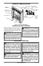
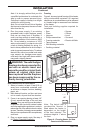
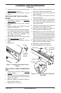
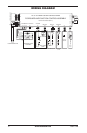
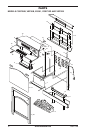
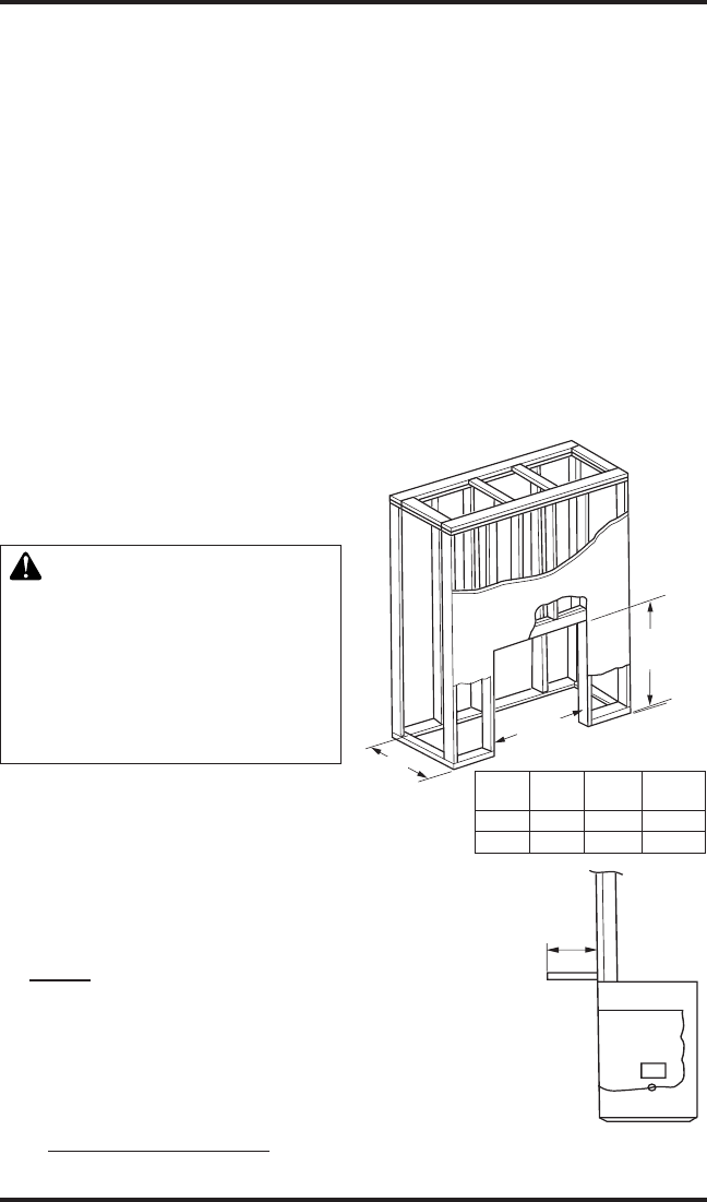
Framing
Figure 4, shows a typical framing of this heater
using combustible materials. All required
clearances to combustibles must be adhered
to. Header height is measured from the base
of the heater.
Tools and building supplies required for
installation:
• Saw • Square
• Pliers • Gloves
• Hammer • Level
• Phillips screwdriver • Surround
• Framing materials • Electric drill/bits
• Tape measure
• Wall-nishing materials
• Caulking material
INSTALLATION
Continued
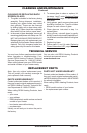
Figure 4 - Framing Heater for New
Construction/Renovation
Length
Header
Height
Depth
0.75"-
0.50"
Model Depth Length
Header
Height
26" 9.75" 27" 26"
32" 10.5" 34" 32"
Note: The height that a
combustible mantel is
tted above the heater is
dependent on the height
of the front selected. The
minimum height is 1" above
the front.