


www.desatech.com
117437-01B10
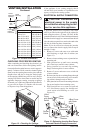
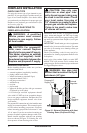
Lowest
Discharge
Opening
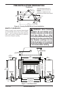
Listed
Vent Cap
8 Ft. Min.
Roof Pitch x/12
Listed Clearance
12
x
Listed
Gas
Vent
H (Min)
Height
From Roof
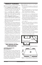
Figure 11 - B-Vent Termination
Roof Pitch H (Min.)
Flat to 6/12 1.0 ft (0.3 m)
6/12 to 7/12 1.25 ft (0.38 m)
Over 7/12 to 8/12 1.5 ft (0.46 m)
Over 8/12 to 9/12 2.0 ft (0.61 m)
Over 9/12 to 10/12 2.5 ft (0.76 m)
Over 10/12 to 11/12 3.25 ft (0.99 m)
Over 11/12 to 12/12 4.0 ft (1.22 m)
Over 12/12 to 14/12 5.0 ft (1.52 m)
Over 14/12 to 16/12 6.0 ft (1.83 m)
Over 16/12 to 18/12 7.0 ft (2.13 m)
Over 18/12 to 20/12 7.5 ft (2.27 m)
Over 20/12 to 21/12 8.0 ft (2.44 m)
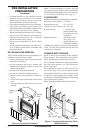
VENTING INSTALLATION
Continued
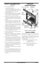
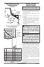
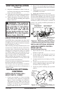
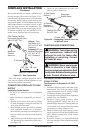
CHECKING FOR PROPER VENTING
After completing and checking the electrical, gas
and vent connections, follow the lighting instruc-
tions and allow the main burner to run for approxi-
mately 5 minutes. Hold a match or butane lighter
ame, near the opening between the glass and the
replace face and play it along the entire length
of the opening (Smoke may also be used). Proper
venting will tend to draw ame or smoke into the
appliance. Improper venting, escaping or spillage
of burned gas, is indicated when the match ickers
or goes out (see Figure 12). Smoke will also tend
to disperse away from the appliance.
Figure 12 - Checking for Spillage
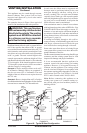
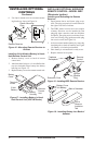
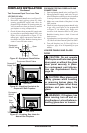
Figure 13 - Relocating Junction Box Recep-
tacle and Electrical Supply Connection
If the appliance is not venting properly, shut it
off and notify your installer or a qualied service
agency to inspect the venting system.
ELECTRICAL SUPPLY CONNECTION
CAUTION: Disconnect the
electrical power to the supply
circuit before attempting to con-
nect or service this appliance.
A prewired junction box receptacle with strain
relief is provided on the right side of the cabinet for
hard wiring the unit to a 15 Amp, 120 VAC, 60 Hz
grounded branch circuit. If the installation demands
that the electrical supply be connected from the left
side, the entire receptacle box can be relocated to the
left side by following these instructions:
Note: If you do not need to relocate the junction
box, to connect the electric supply follow steps 8
through 11 only:
1. Remove 2 screws and outer cover with strain
relief bushing on right side of cabinet (see
Figure 13).
2. Remove inner retaining screw on junction box
mounting tab.
3. Slide junction box up until screw mounting
tab is lined up to notch in outer cabinet.
4. Swing junction box out and slip retaining
ange out through slot in outer cabinet.
5. Remove 2 screws and outer cover on left side
of outer cabinet.
6. Reinsert junction box retaining ange through
slot now on left side and swing screw mount-
ing tab back through notch as before.
7. Slide junction box down till mounting tab holes
line up and replace inner retaining screw.
8. With junction box cover removed, pull end
of 3-wire Romex supply line through uni-
versal strain relief bushing on cover. (see
Figure 13).
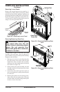
J-Box
Cover
with Strain
Relilef
J-Box
Cover
Romex
Cable
J-Box with
Receptacle
J-Box Cover
with Strain
Relief
Screw/Tab
Retainer