www.desatech.com
115603-01C6
FIREPLACE INSTALLATION
Continued
Woodwork such as wood trims, mantels or
any other combustible material projecting from
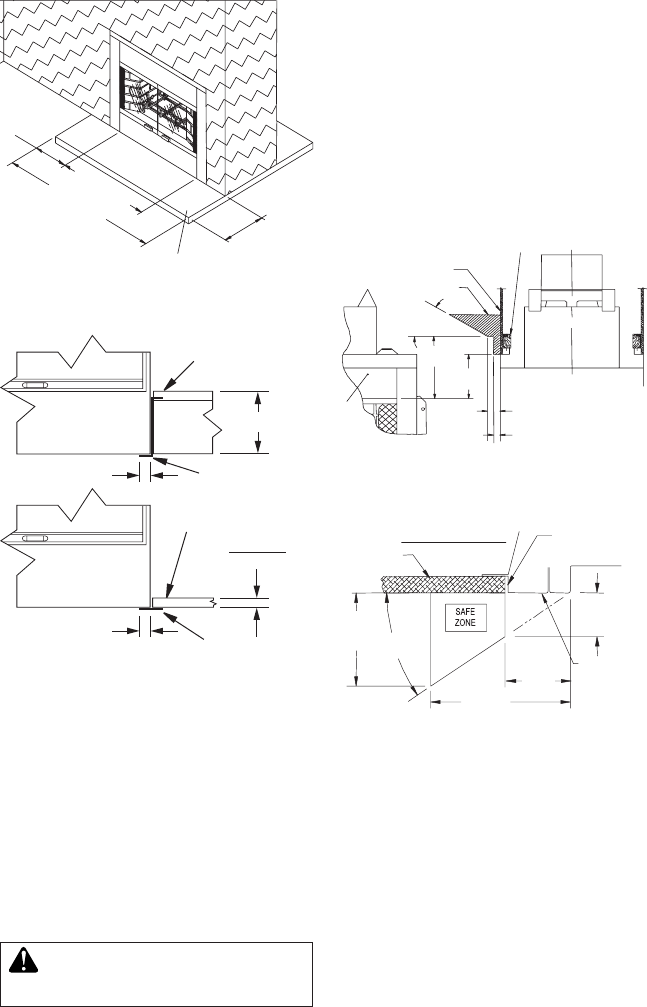
Figure 12 - Mantel Clearances to Metal
Face
VENTING INSTALLATION
8" Max.
“K” Facto
r
.84
1
1
/2" Typ.
1
1
/2" Typ.
Noncombustible
Hearth
Extension
“Z” Type Ember
Protector
Noncombustible
Hearth Extension
Ember Protector
Figure 10 - Raised Hearth Extension
Front
Face
Fireplace Front View
Fireplace Side View
3" Nom.
(7.6 cm)
9" Min.
(22.8 cm)
12" Min.
(30.4 cm)
33°
6" Nom.
(15.2 cm)
1
1
/
2
" Max.
(3.8 cm)
Drywall
2" X 4" Stud
Combustible
Materials
Figure 11 - Mantel Clearances to
Combustible Materials
Seal Gaps with
Noncombustible
Mortar or Adhesive
Top View of Fireplace
Drywall
4"
(Approx.)
(10.1 cm)
33°
Nom.
6" Nom.
(15.2 cm)
4
3
/
8
"
Min.
(11.1 cm)
Combustible
Material Must
Not Overlap
Black Metal
Front Face
2
3
/
4
" Max.
(6.98 cm)
NONCOMBUSTIBLE
HEARTH EXTENSION
52
1
/
2
" MIN.
(133.3cm)
36
1
/
2
" MIN.
(92.7cm)
8" MIN.
(20.3cm)
16" MIN.
(40.6cm)
Figure 9 - Hearth Extensions
the front face must not be placed within 9" of
replace opening.
Combustible materials above and projecting
more than 1
1
/
2
" from the replace front face
(see Figure 11) must not be placed less than 12"
from effective opening of the replace (NFPA
STD 211, Sec. 7-3.3.3).
Mantels or any other combustible material
may also come up to the side edge of the
black metal face of the replace only if the
projection from the front face falls within limits
shown in Figure 12.
The installation of an outside air kit should
be performed during the rough framing of
the replace due to the nature of it’s location.
Outside combustion air is accessed through
and exterior wall or a vented crawl space.
not terminate in attic space.
Maximum height for air inlet above the re-
place platform must be no less than 3 feet
below chimney cap.
For further details on installation of outside
air kit, please refer to instructions included
with air kit.


