www.desatech.com
120948-01A6
ASSEMBLY
Continued
5.
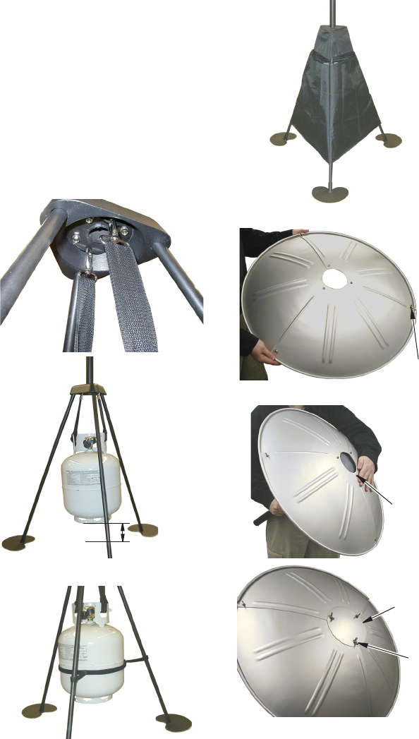
Install tank straps to base as (see Figure 5).
6. Install tank restraint to tank and fasten
restraint straps around legs as shown in
Figure 6.
7. Install the tank cover (see Figure 7).
8. Assemble reector with small wing nuts
and bolts as shown in Figure 8.
9. Install reector over post on top of burner
assembly. Install reector cap over post.
Attach reector and reector cap using
large wing nuts (see Figure 9).
Figure 7 - Tank Cover
Figure 9 - Attaching Reector and
Reector Cap to Burner Assembly
Figure 5 - Attaching Tank Straps to Base
Figure 6 - Tank Restraint Straps
Figure 8 - Reector Assembly
Bolts on
Top of
Burner
Assembly
Reector
Cap
Wing
Nut
Wing Nuts
and Bolts
Min. 2" from
Tank to Ground


