


19
104024
WARNING ICON G 001
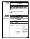
WARNING
Do not operate heater between PILOT and HIGH positions.
WARNING ICON G 001
CAUTION
Do not try to adjust heating levels by using the manual shutoff valve.
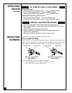
VARIABLE CONTROL OPERATION
The variable control valve can be set to any heat setting and flame height desired, by
simply turning the control knob until that setting is attained. Even the lowest setting
provides realistic, dancing yellow flames. Selecting higher settings produces greater
heat output. This results in increased heating comfort.
4. Wait five (5) minutes to clear out any gas. Then smell for gas, including near the
floor. If you smell gas, STOP! Follow “B” in the safety information on page 18 . If
you don’t smell gas, go to the next step.
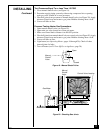
5. Slightly depress and turn control knob counterclockwise
C-clockwise
to the PILOT
position. Keep control knob pressed in for five (5) seconds (see Figure 21, page 18).
Note:
You may be running this heater for the first time after hooking up to gas
supply. If so, the control knob may need to be pressed in for 30 seconds. This
will allow air to bleed from the gas system.
6. With control knob pressed in, press and release ignitor button. This will light
pilot. The pilot is attached to the burner (see Figure 16, page 14). If needed, keep
pressing ignitor button until pilot lights.
Note:
If pilot does not light, contact a qualified service person or gas supplier
for repairs. Until repairs are made, light pilot with match. To light pilot with
match, see Manual Lighting Procedure on page 20.
7. Keep control knob pressed in for 30 seconds after lighting pilot. After 30 seconds,
release control knob.
Note:
If pilot goes out, repeat steps 3 through 7.
• If control knob does not pop out when released, contact a qualified service
person or gas supplier for repairs.
OPERATING
HEATER
Continued
8. Slightly depress and turn control knob counterclockwise
C-clockwise
to the HIGH
position. The burner should light. Set control knob to any heat level between
HIGH and LO.
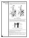
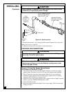
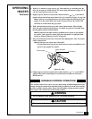
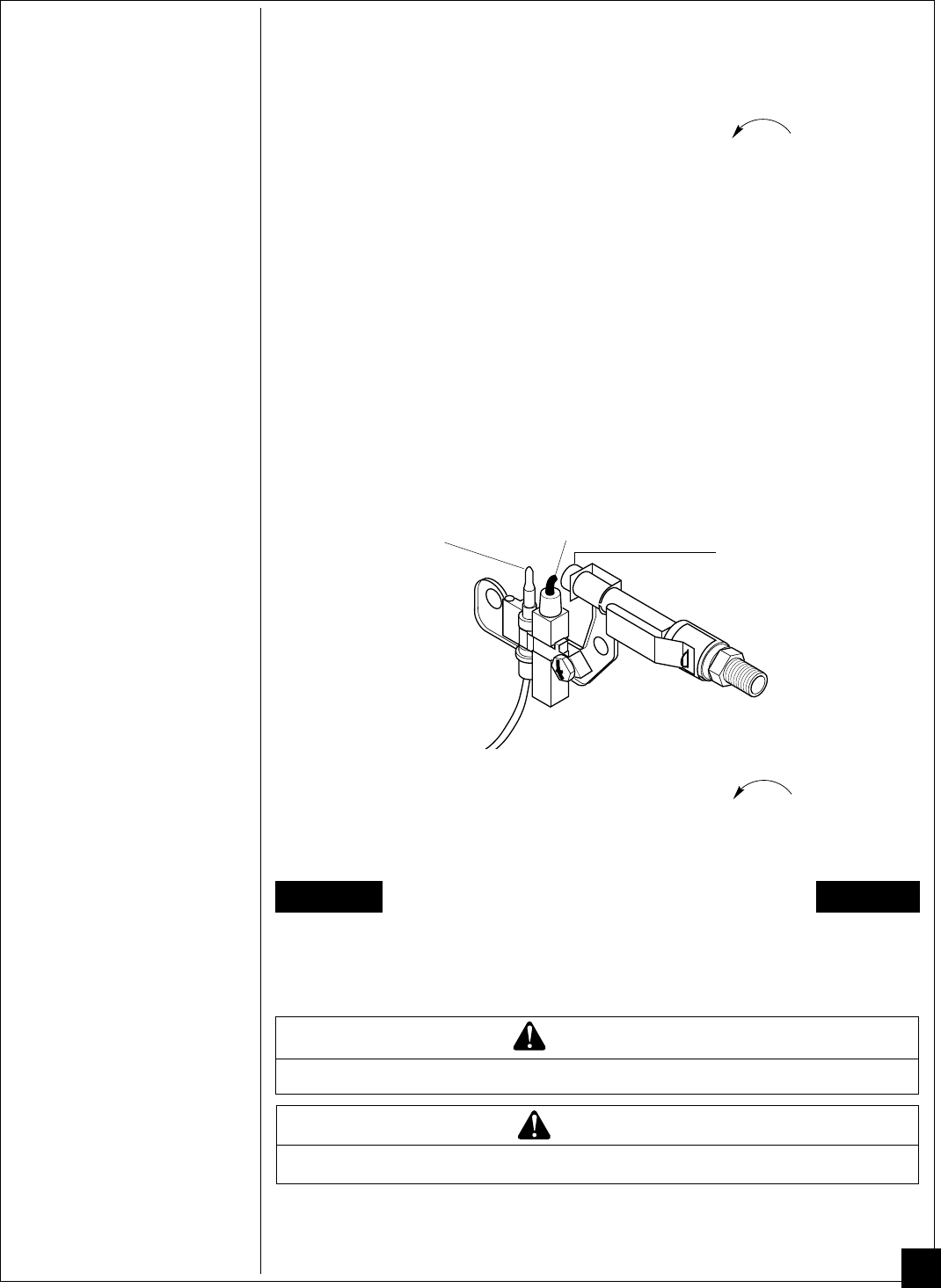
Figure 22 - Pilot
Thermocouple
Ignitor Electrode
Pilot Burner
Continued