


www.desatech.com
114744-01B
20
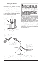
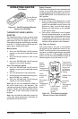
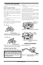
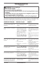
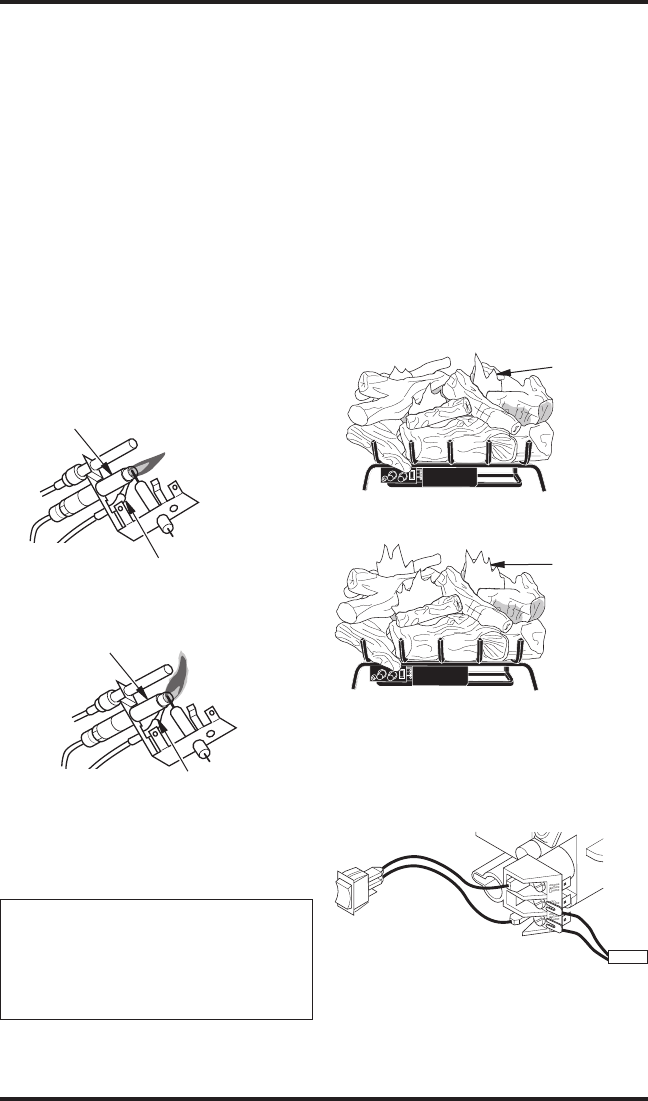
BURNER FLAME PATTERN
Figure 25 shows correct burner flame pattern.
NOTICE: Do not mistake orange
flames with yellow tipping. Dirt
or other fine particles are burned
by heater, causing brief patches
of orange flame.
Figure 25 - Correct Burner Flame Pattern
Figure 26 - Incorrect Burner Flame
Pattern
Blue and
Bright Yellow
Flames
Darker
Orange
Flames
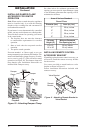
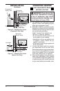
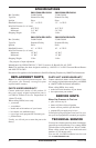
WIRING DIAGRAM
When Using Remote
A
U
T
O
O
F
F
ON
Thermopile
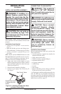
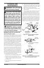
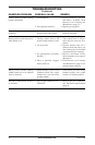
INSPECTING BURNER
Check pilot flame pattern and burner flame pat-
terns often.
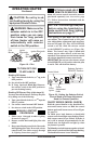
PILOT FLAME PATTERN
Figure 23 shows a correct pilot flame pattern.
Figure 24 shows an incorrect pilot flame pattern.
The incorrect pilot flame is not touching the
thermocouple. This will cause the thermocouple
to cool. When the thermocouple cools, the heater
will shut down.
If pilot flame pattern is incorrect, as shown in
Figure 24
• turn heater off (see To Turn Off Gas to Appli
-
ance, page 18)
• see Troubleshooting
, page 22
Note: The pilot flame on natural gas units will
have a slight curve, but flame should be blue and
have no yellow or orange color.
Figure 23 - Correct Pilot Flame Pattern
(Your pilot may vary from pilots shown)
Pilot Burner
Thermocouple
Figure 24 - Incorrect Pilot Flame Pattern
(Your pilot may vary from pilots shown)
Pilot Burner
Thermocouple
If burner flame pattern is incorrect, as shown in
Figure 26
• turn heater off (see To Turn Off Gas to Appli
-
ance, page 18)
• see Troubleshooting
, page 22
The flames from the burner travel horizontally
through the log set and emerge at the middle and
rear of the set against the back logs.
The flames are blue off the burner and as they
progress through the log set, change to a light
yellow color, yellow decorative flames are visible
as the flames exit the log set.
The base of the log set and the underside of the
top logs glow red. Natural gas models will burn
with more blue flame, while propane gas model
will burn with bright yellow flame.
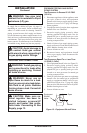
Figure 27 - Connecting Remote Receiver
to Control Valve