


4
102553
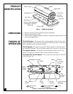
PRODUCT
IDENTIFICATION
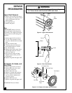
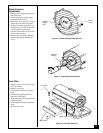
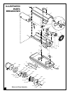
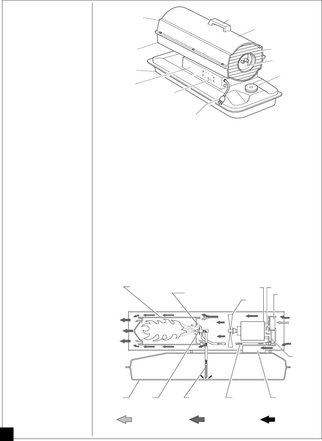
Figure 2 - Cross Section Operational View
Fuel
Filter
Air Line
To Burner
Air
Output
Filter
Air Pump
Air Intake
Filter
Cool
Air
In
Fan
Combustion Chamber
Ignitor
Motor
Clean
Heated
Air Out
Ignition Control
Assembly
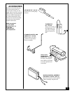
Figure 1 - 50,000 Btu/Hr Model
Handle
Fuel Cap
Lower Shell
Power Cord
Fuel Tank
Hot Air Outlet
Air Filter
End Cover
Fan Guard
Upper Shell
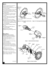
Air For Fuel
System
Air For Combustion
And Heating
Fuel
Side Cover
Ignition Control Assembly
(assembly on inside of
side cover)
Nozzle
THEORY OF
OPERATION
The Fuel System: The air pump forces air through the air line. The air is then
pushed through the nozzle. This air causes fuel to lift from the tank. A fine mist of
fuel is sprayed into the combustion chamber.
The Air System: The motor turns the fan. The fan pushes air into and around
the combustion chamber. This air is heated and provides a stream of clean, hot air.
The Ignition System: The ignition control assembly provides power to the
ignitor. This ignites the fuel/air mixture in the combustion chamber.
The Flame-Out Control System: This system causes the heater to shut down
if the flame goes out.
1. Remove all packing items applied to heater for shipment.
2. Remove all items from carton.
3. Check items for shipping damage. If heater is damaged, promptly inform dealer
where you bought heater.
UNPACKING
Fuel
Tank