


www.desatech.com
104787-01D 9
SPECIFICATIONS
• Rating: 30,000 BTU/Hr (31,644 kj/Hr)
• Fuel: Propane Vapor Only
• Fuel Consumption/Hour: 0.33 U.S. gallons
(1.24 liters), 1.39 lb (0.63 kg)
• Supply Pressure To Regulator: Minimum**-
20 psi (138 kPa), Maximum - Tank Pressure or
200 psi (1380 kPa)
• Regulator Outlet Pressure: 10 psi (69 kPa)
• Manifold Pressure: 10.1 psi (69 kPa)
• Hot Air Output (CFM Approx): 175 (4.95 m
3
)
• Motor: 3045 RPM, 1/40 HP
• Electric Input: 120 volt/60 hertz
• Amperage: 0.6
• Ignition: Manual, Piezo
•
Temperature Range for Operation: -20° to 85° F*
(-6.7° to 29.5° C*)
• Heater Weight: 11 lb (4.99 kg)
• Shipping Weight: 13 lb (5.90 kg)
• Size (L x W x H): Carton - 19.4" x 9.75" x 14.75"
(49.3 x 24.8 x 37.5 cm),
Heater - 18.5" x 8.0" x 12.8" (47 x 22.32 x 32.5 cm)
* When running heater in temperatures above
85° F (29.5° C), high internal temperatures may
cause thermal limit device to shut down heater.
** For purposes of input adjustment.
IGNITOR
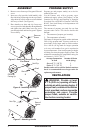
1. Remove motor and fan guard from heater (see
Motor, page 8, steps 1 and 2).
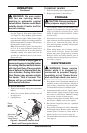
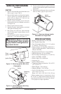
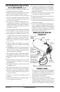
2. Remove black ignitor wire from piezo ignitor.
Access ignitor wire through underside of
heater base (see Figure 13). Push wire up
through notch in filler panel.
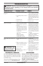
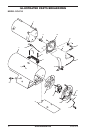
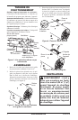
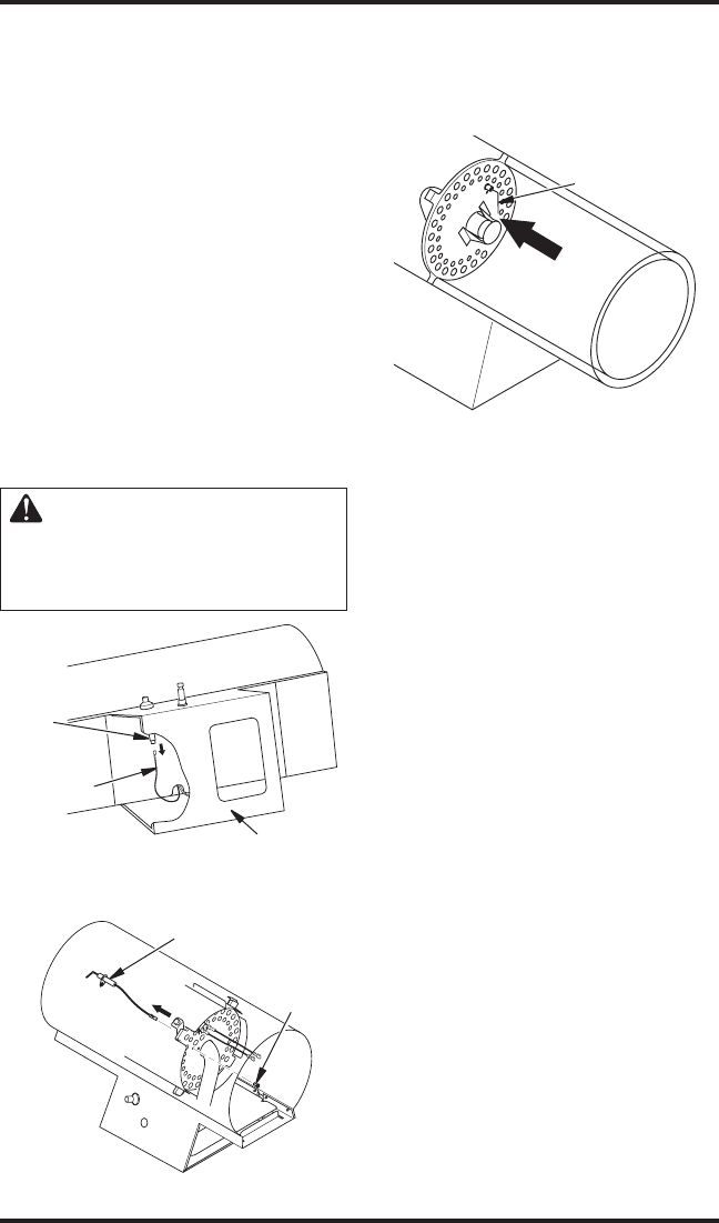
3. Remove ignitor mounting screw from rear
head using nut-driver or standard screwdriver
(see Figure 14).
4. Remove ignitor from rear head.
5. Install new ignitor. Attach ignitor to rear head
with ignitor mounting screw.
6. Run ignitor wire from new ignitor through
notch in filler panel. Attach ignitor wire to
piezo ignitor.
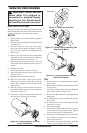
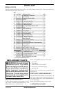
7. Set gap between ignitor electrode and target
plate to 0.17" (4.3 mm) (see Figure 15).
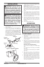
WARNING: Make sure heater
is disconnected from propane
supply. Heater could ignite caus
-
ing severe burns.
SERVICE PROCEDURES
Continued
Figure 13 - Removing Ignitor Wire from
Piezo Ignitor
Ignitor Wire
Piezo
Ignitor
Underside of Heater
Figure 14 - Removing Ignitor Mounting
Screw and Ignitor
Ignitor
Mounting
Screw
8. Test for spark. Push piezo ignitor button and
watch for spark between ignitor electrode and
target plate.
9. Place motor and fan guard into rear of heater
shell (see Motor, page 8, steps 8 and 9).
Figure 15 - Clearance between Ignitor
Electrode and Target Plate
Ignitor
Electrode
Gap
Area