


115425-01
4
For more information, visit www.desatech.com
INSTALLATION
WARNING: Before installing in a solid fuel burning
fi replace, the chimney fl ue and fi rebox must be cleaned
of soot, creosote, ashes and loose paint by a qualifi ed
chimney cleaner. Creosote will ignite if highly heated.
A dirty chimney fl ue may create and distribute soot
within the house. Inspect chimney fl ue for damage. If
damaged, repair fl ue before operating heater.
NOTICE: Installation, service, and repair of this appli-
ance must be performed by a qualifi ed installer, service
agency, company or gas supplier experienced with
this type of gas appliance. Only factory authorized
components listed in these instructions may be used
in accordance with the manufacturer’s instructions
and all codes and requirements of the authority hav-
ing jurisdiction. Any modifi cations to this kit, or use
of unauthorized components or accessory items will
void the manufacturer’s warranty, and may result in
a hazardous condition.
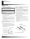
CHECK GAS TYPE
Use only natural gas. If your gas supply is not natural gas, you
MUST NOT install this gas log set
If the fi replace does not have a gas supply shutoff valve, one must
be installed.
CAUTION: Do not remove the data plates attached
to the burner pan. The data plates contain important
warranty information.
FLUE OPENING SPECIFICATIONS
Note: This vented appliance must be installed only in a solid-fuel
burning fi replace with a working fl ue and constructed of noncom-
bustible material.
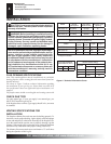
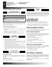
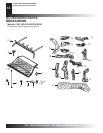
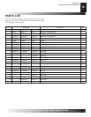
The charts in Figure 2 indicate technical information regarding
the installation of your gas log set. Please make sure that all of
the specifi cations shown are applicable before installation is at-
tempted.
The fi replace must include a working fl ue and venting system with
VENTING SPECIFICATIONS FOR
INSTALLATION
The fi replace chimney fl ue and vent must be drafting properly. To
check the vent for proper drafting: Light a tightly rolled newspaper
on one end and place it at the inside front edge of the fi replace. Ob-
serve the smoke and be sure the vent is properly drawing it up the
chimney. If the smoke spills out into the room, extinguish the fl ame
and remove any obstruction until proper venting is achieved.
The chimney fl ue must remain open a minimum of 3" at all times
during the operation of this log set.
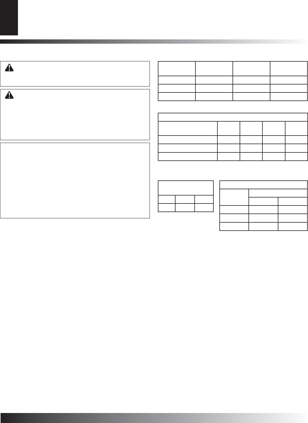
Figure 2 - Technical Information Charts
INSTALLATION
Flue Opening Specifi cations
Check Gas Type
Venting Specifi cations for Installation
Model
Burner
Description
BTU Input
(Natural Gas)
Minimum Vent
Opening
PHK/ BCS 18 18" Ramp 57,000 8"
PHK/ BCS 24 24" Ramp 80,000 8"
PHK/ BCS 30 30" Ramp 90,000 8"
Minimum Fireplace Dimensions
Model
Front
Width
Back
Width*
Depth Height
PHK/ BCS 18 28" 18" 16" 18"
PHK/ BCS 24 36" 23" 16" 18"
PHK/ BCS 30 42" 29" 18" 18"
* At depth Indicated
Fuel Inlet Pressure
Specifi cations (W.C.)
Min. Max.
N.G. 5.5" 10.5"
Burner Orifi ce Sizing
Log Size
Natural Gas
In. Num.
18" .120 31
24" .140 28
30" .1495 25