


www.desatech.com
19118621-01B
+
+
1
9
13
5
7
3
11
15
A
M
E
G
C
K
I
O
1
9
13
7
5
3
11
15
OFF REMOTE
A
M
E
G
C
K
I
O
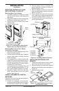
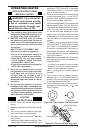
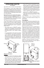
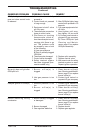
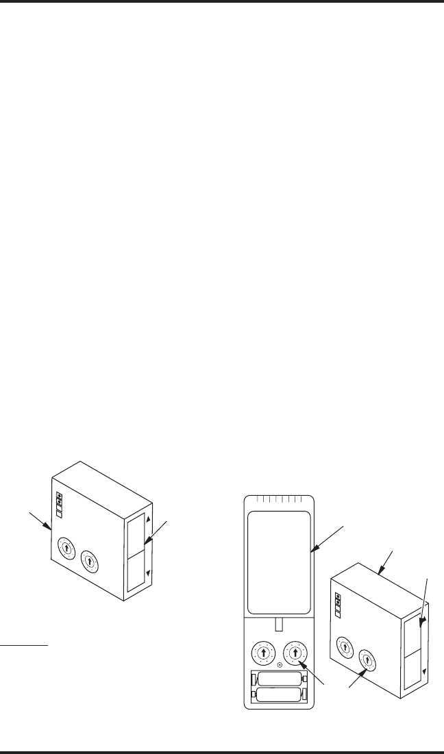
Figure 27 - Receiver
Slide
Switch
Receiver
+
+
1
9
13
5
7
3
11
15
A
M
E
G
C
K
I
O
1
9
13
7
5
3
11
15
OFF REMOTE
A
M
E
G
C
K
I
O
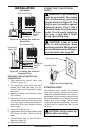
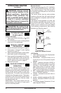
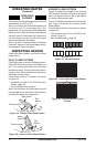
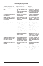
Figure 28 - Receiver and Remote Control
Setup
Slide
Switch
Code
Switches
Receiver
Back of
Remote
Control
Note: When lock-out mode is activated letters
CP will appear in room temp window. After
activation is complete room temp window will
default back to displaying room temperature.
If any buttons are pressed room temp window
will then display CP indicating remote control
is in lock-out mode.
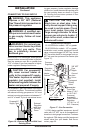
Remote Receiver (located inside heater)
The remote receiver operates on 4 AA 1.5V
batteries (included). IMPORTANT: New or
fully charged batteries are essential for proper
operation of the remote receiver.
The remote receiver houses the micropro-
cessor that responds to commands from
remote control to control system operation.
The remote receiver has a 2 position slide
switch for selecting the mode of operation:
REMOTE/OFF
• With slide switch in REMOTE position,
system will only operate if remote receiver
receives commands from remote control.
• With slide switch in OFF position, system
is off.
• It is suggested that slide switch be placed
in OFF position if you will be away from
your home for an extended period of time.
Placing slide switch in OFF position also
functions as a safety lock out by both turn-
ing system off rendering remote receiver
inoperative.
OPERATING HEATER
Continued
• When OFF button is pressed the remote
control sends a RF signal to the receiver.
The receiver then sends a pulse of 6 volts
of power to the solenoid. The solenoid then
closes gas ow to burner then to full OFF.
• Heater will only work with hand held remote
control. Receiver slide switch is only for
positive OFF or REMOTE operation.
• The remote control will only operate heater
when pilot is lit and control knob is in the
ON position.
Note: Extensive use of latching solenoid
(ON/OFF) will reduce receiver’s battery life
signicantly.
Code Setting
IMPORTANT: All units are shipped from fac-
tory with code switch preset to same codes.
These switches must be reset to different
codes during installation to prevent interfer-
ence from another remote.
Each transmitter can use one of 255 security
codes that can be reset. It WILL be neces-
sary to set remote control and receiver code
switches to a matching security code upon
initial use. If a replacement remote control
or receiver is purchased from your dealer or
factory, code switches must be set to match
receiver and remote control code switches.
When setting code switches, set A through P
switch on remote control to same setting as
A through P switch on receiver. Then set 1
through 16 switch on remote control to same
setting as 1 through 16 switch on receiver.
Note: A small screwdriver can be used to
change these code switches.
General Information
Operation
•
This remote control will operate gas valves
latching solenoid to open gas ow to full ON.
• When ON button is pressed the remote
control sends a RF signal to the receiver.
The receiver then sends a pulse of 6 volts
of power to the solenoid. The solenoid then
opens gas ow to burner then to full ON.